LiftMaster IPACIPDCC IPACIPDCC Door Controller Installation Manual - Page 7
Ipc−3b−yyww
 |
View all LiftMaster IPACIPDCC manuals
Add to My Manuals
Save this manual to your list of manuals |
Page 7 highlights
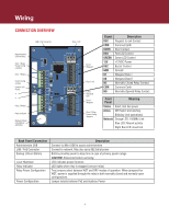
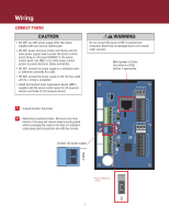
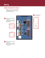
Wiring ADD CONTROL PANEL NC COM NO NC COM NO NC COM NO NC COM NO -12IN+ ADMIN LAN DRY PoE WET DRY PSE1 RLY1 RLY2 IO 2 REX READER 1 IO 1 REX COM DOOR COM DOOR RED GRN 12V BUZ GND D1 D0 1 Connect IPDC to the Internet (Ethernet, DSL, or cellular modem). HRTBT READER 2 RED GRN 12V BUZ GND D1 D0 WET IPACIPDCC Access Control Panel INPUT RATINGS: SECURITY 12IN: 12VDC 1500mA PoE: 42 57VDC 13W C US Date: 2014/36 LISTED MAC: 00:1D:00:00:92:CF CP# IPC−3B−YYWW 2 Write down Control Panel number (on base of IPDC cover). IPC 3 Mount the unit to the mounting plate being careful to push any excess wire through the mounting plate and into the junction box. Replace retaining screw through bottom of cover and into the mounting plate. 7
-
 1
1 -
 2
2 -
 3
3 -
 4
4 -
 5
5 -
 6
6 -
 7
7 -
 8
8
 |
 |

7
SECURITY
LISTED
IPACIPDCC
IPC−3B−YYWW
US
C
Access Control Panel
INPUT RATINGS:
12IN:
PoE:
42 57VDC 13W
Date: 2014/36
MAC:
CP#
00:1D:00:00:92:CF
12VDC 1500mA
LAN
ADMIN
DRY
RLY1
WET
PSE1
PoE
DRY
WET
RLY2
HRTBT
READER 1
IO
1
REX
COM
DOOR
RED
GRN
12V
BUZ
GND
D1
D0
IO
2
REX
COM
DOOR
READER 2
RED
GRN
12V
BUZ
GND
D1
D0
NC
COM
NO
NC
COM
NO
NC
COM
NO
NC
COM
NO
-12IN+
Connect IPDC to the Internet
(Ethernet, DSL, or cellular
modem).
Mount the unit to the mounting plate being careful to push any excess wire through the mounting
plate and into the junction box. Replace retaining screw through bottom of cover and into the
mounting plate.
1
Wiring
2
Write down Control Panel number (on base
of IPDC cover).
IPC – _ _ – _ _ _ _ _
3
ADD CONTROL PANEL