LiftMaster LMSC1000 Installation Manual - English French Spanish - Page 20
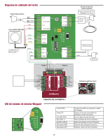
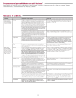
Diagrama de cableado del lector, LED del módulo de interfaz Wiegand
 |
View all LiftMaster LMSC1000 manuals
Add to My Manuals
Save this manual to your list of manuals |
Page 20 highlights
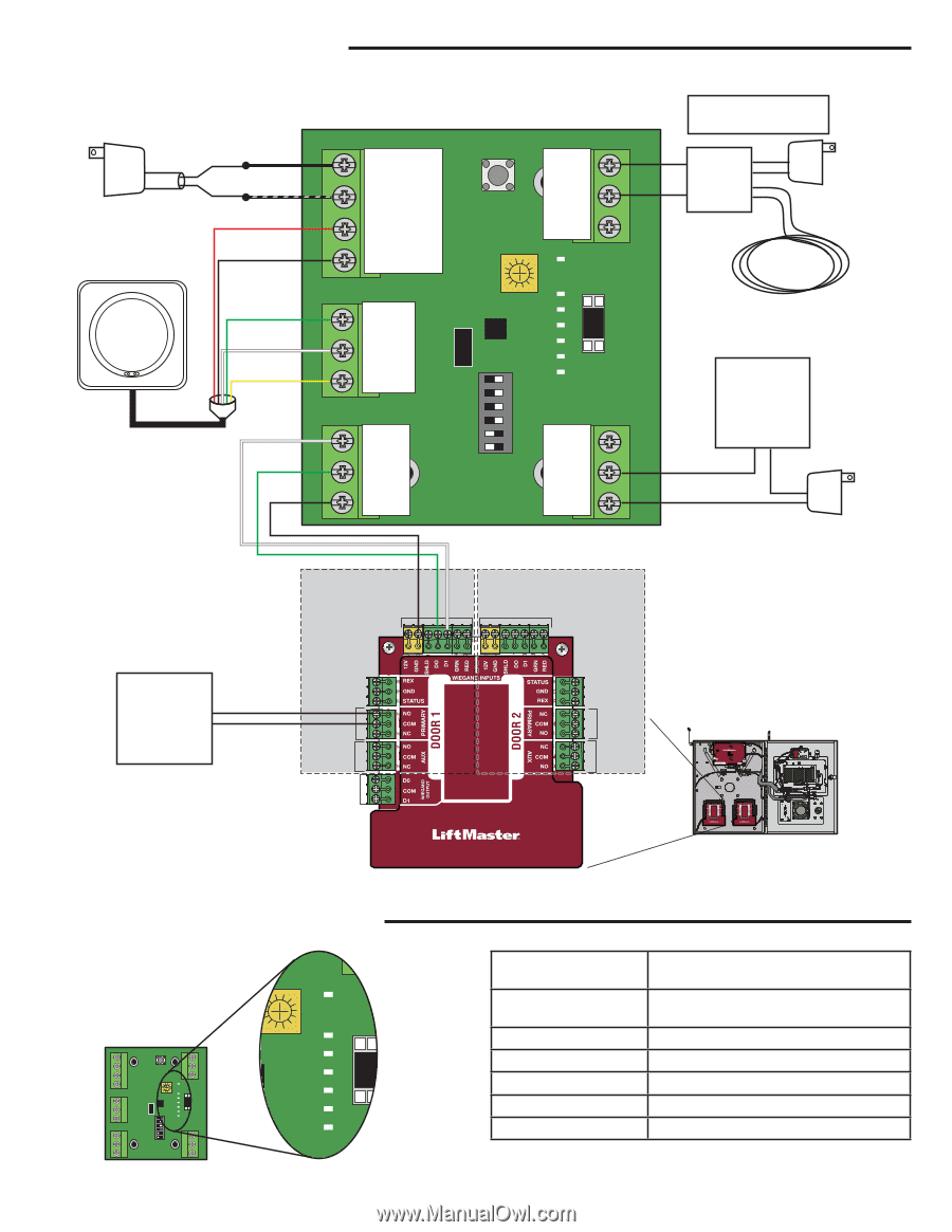
Diagrama de cableado del lector Transformador eléctrico Negro Negro c/rayas Lector de RFID LMSC1000 Rojo Negro Verde Blanco Amarillo Los cables gris, azul y marrón del lector de RFID no se usan. Blanco Verde Negro Power +12 V RESET - 12 VCC (GND) Loop TIERRA LP_INL +12 V LP_INH - 12 VCC (GND) Serial SER IN SER OUT TIERRA Wiegand DATA 1 DATA 0 PWR RF PWR SET LP SET/ERR SER I SER 0 WO SETUP 6 DC LOOP 5 8SEC 4 4SEC 3 Dry Cont 2SEC 2 1SEC 1 NO CONN ON - OFF A TIERRA B Puerta 1 Puerta 2 ENTRADA WIEGAND ENTRADA WIEGAND Detector de bucle de armado (opcional) Colocar el interruptor N.° 5 en "ENCENDIDO" para activar. Detector de bucle de armado Operador de portón o luz de bajo voltaje Normalmente abierto Común 24 voltios CA/CC 1 amperio máx. PEDIDO DE SALIDA ESTADO RELÉ PRIMARIO RELÉ AUXILIAR WIEGAND OUTPUT ESTADO PEDIDO DE SALIDA RELÉ PRIMARIO RELÉ AUXILIAR Sistema de control de acceso ON TARJETA DE LA PUERTA 1 LED del módulo de interfaz Wiegand Verde (PWR) PWR Verde (LP) Power Serial Wiegand RESET Loop PWR RF PWR SET LP SET/ERR SER I SER 0 WO SETUP 6 DC LOOP 5 8SEC 4 4SEC 3 2SEC 2 1SEC 1 ON - OFF Dry Cont LP SET/ERR SER I SER 0 WO DC 6 5 Azul (SET/ERR) Rojo (SER 1) Amarillo (SER 0) Anaranjado (W0) Anaranjado (DC) 20 Energía (Encendido sin parpadear cuando hay energía) Detector de armado (Encendido sin parpadear cuando está activo) Error de datos recibido del lector Datos recibidos del lector (Parpadeo) Datos transmitidos al lector (Parpadeo) Salida de datos Wiegand (Parpadeo) Salida de control del relé (Parpadeo)
-
 1
1 -
2
-
3
-
4
-
5
-
6
-
7
-
8
-
9
-
10
-
11
-
12
-
13
-
14
-
 15
15 -
 16
16 -
 17
17 -
 18
18 -
 19
19 -
 20
20 -
 21
21 -
 22
22 -
 23
23 -
 24
24
 |
 |