LiftMaster LMSC1000 Installation Manual - English French Spanish - Page 3
Wiegand Interface Module, Mounting and Wiring, Arming Loop Input Optional, Dry Contact Relay Output
 |
View all LiftMaster LMSC1000 manuals
Add to My Manuals
Save this manual to your list of manuals |
Page 3 highlights
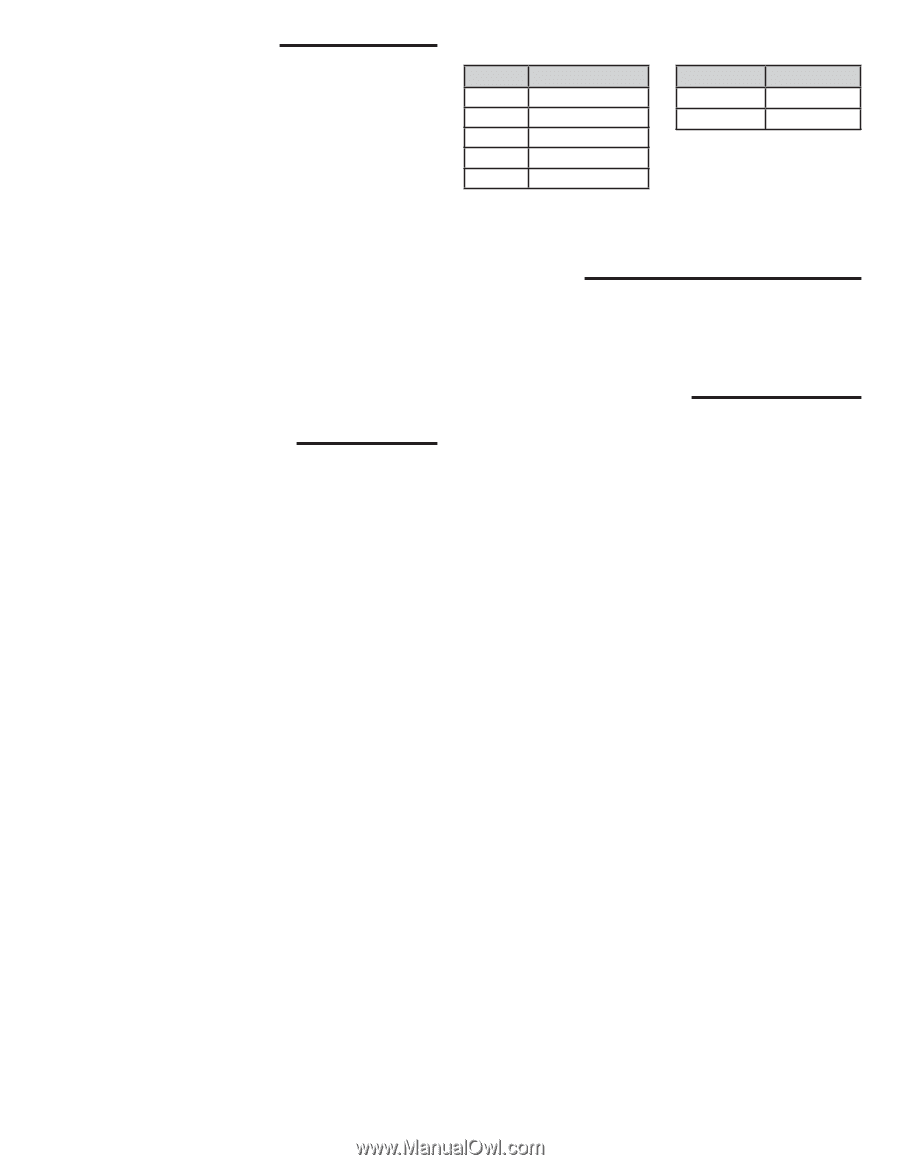
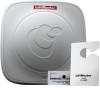
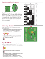
Wiegand Interface Module Mounting and Wiring The following are the provisions for the wiring connections on the LMSC1000 reader system. • Take special precautions to protect the system's components by locating them in a weatherproof enclosure (sold separately). • In the weatherproof enclosure, provide a properly protected 115VAC power outlet for powering the reader through the provided power supply. • Once an appropriate weatherproof enclosure with power outlet has been installed, route the reader cable so that it safely enters the enclosure and maintains the enclosure's weatherproof capabilities. • Route Wiegand Data 0, Data 1, and Common from S2W Wiegand Interface to the access control panel so that it safely exits the enclosure and maintains the enclosure's weatherproof capabilities. • AC must be run in a separate conduit. • Maximum cable distance between Reader and S2W Wiegand Interface is 19 feet (5.8 m). • Maximum cable distance between S2W Wiegand Module Interface and access control system is 350 ft (107 m) with 18 AWG wire. • Maximum cable distance between the relay control of the S2W and an external visual/audible device is 98.5 ft. Arming Loop Input (Optional) For applications where multiple RFID readers will be in close proximity this feature can be used to turn on the reader field ONLY when the loop senses the presence of a vehicle. When switch 5 is turned on, the Wiegand board sends a command to the antenna to turn off the reader field until a vehicle presence is detected. Reader Cable Index Color Yellow Green White Black Red Function Com TXD RXD -12V DC (GND) +12V DC Power Supply Index Color Solid Black Black w/Dash Function +12V DC - 12V DC (GND) Reader LEDs The LEDs on the front of the LMSC1000 Reader will illuminate red when powered. Blinking blue LEDs indicate an RFID tag is being read. Dry Contact Relay Output For applications where RFID tag holders want an external visual or audible notification that the reader processed their tag. The relay contacts change state for 2 seconds with every valid Wiegand output, if time delay is enabled the relay will only pulse once during the selected period. Low voltage only, 24 Volts AC/DC 1 amp 3
-
 1
1 -
 2
2 -
 3
3 -
 4
4 -
 5
5 -
 6
6 -
 7
7 -
 8
8 -
 9
9 -
10
-
11
-
12
-
13
-
14
-
15
-
16
-
17
-
18
-
19
-
20
-
21
-
22
-
23
-
24
 |
 |