LiftMaster T T- Mechanical New style with thermal overload Manual - Page 4
Installation Instructions, Important Note, Mount Header Bracket, Mount Operator - rail
 |
View all LiftMaster T manuals
Add to My Manuals
Save this manual to your list of manuals |
Page 4 highlights
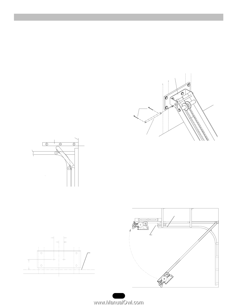
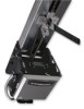
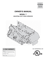
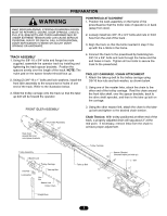
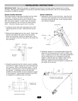
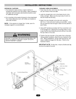
INSTALLATION INSTRUCTIONS IMPORTANT NOTE: Before the operator is installed, be sure the door has been properly aligned and is working smoothly. Although each installation will vary due to particular building characteristics, refer to the following general procedures to install the operator. MOUNT HEADER BRACKET The trolley operator is generally mounted over the center of the door. However, off center mounting may be required due to interfering structures or location of door stile / top section support. In such cases, the operator may be mounted up to 24" off center on torsion spring doors. Extension springs require center mounting. 1. Locate the center of the door and mark a line on the wall directly above the door. Extend this line up the wall. MOUNT OPERATOR 1. Allowing the motor to rest on the floor, raise the front end of the track assembly to the front header bracket and fasten using the 3/8" dia. x 6.40" long pivot shaft and cotterpins supplied. Header Bracket 2. Determine the highest point of door travel. Slowly raise the door and observe the action of the top section. When the top section reaches its highest point, use a level and project a line from this point to the center line the of the door. Cotterpins Carpenter's Level Header Wall High Point of Travel Pivot Shaft Door Travel Projection 3. Using the projected lines for location, mount a suitable wood block or length of angle iron to the wall above the door opening. Refer to the illustration below. This will provide a mounting pad for the front header bracket of the operator. If necessary reinforce the wall with suitable mounting brackets to ensure adequate support of mounting pad. Using suitable hardware, mount the (U shaped) front header bracket to the pad. 3.50" 1.75" 2. Swing the operator to a horizontal position above the guide rails and temporarily secure with a suitable rope, chain, or support from the floor. Now open garage door slowly, being careful not to dislodge the temporary support. Using the door as a support, place a level against the rail and shim the operator until it is horizontal. Make sure that the operator is aligned with the center line of the door. Guide Rails Using the door as support, shim operator to a horizontal position. 4" MIN. High Rise Point Projection Line Vertical Center Line of Door Header Bracket Drill Pattern 4
-
 1
1 -
 2
2 -
 3
3 -
 4
4 -
 5
5 -
 6
6 -
 7
7 -
 8
8 -
 9
9 -
 10
10 -
11
-
12
-
13
-
14
-
15
-
16
-
17
-
18
-
19
-
20
 |
 |