LiftMaster T T- Mechanical New style with thermal overload Manual - Page 5
Operator, Support, Straight Arm Attachment, Important Note - trolley not moving
 |
View all LiftMaster T manuals
Add to My Manuals
Save this manual to your list of manuals |
Page 5 highlights
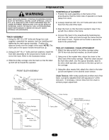
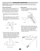
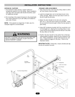
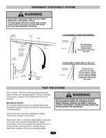
INSTALLATION INSTRUCTIONS CAUTION WARNING OPERATOR SUPPORT STRAIGHT ARM ATTACHMENT 1. The illustration below shows a typical method of 1. Fully close the door and move the trolley slider to within hanging the operator from the ceiling. Each installation (2") two inches of the front idler. may vary, but in all cases side braces should be used for additional strength. 2. Latch the straight door arm to the fixed roll pin in the trolley carriage. Make sure the open side of notch on 2. For mounting of the support brace(s) to the powerhead, the arm faces the doorway. Four holes (clearance up to 3/8" bolts) are located on each side of frame. 3. Attach the door bracket to the door arm using the 3/8"-16 x 1" bolt and nylon locking nut provided. Leave NOTE: If the operator is longer than 15 feet, use of a the nut and bolt loose enough to allow the two pieces to mid-span support is recommended. pivot freely. WARNING FAILURE TO SUSPEND THE OPERATOR SECURELY MAY RESULT IN SERIOUS PERSONAL INJURY OR DEATH, AND/OR PROPERTY DAMAGE. 4. Using 3/8" hardware provided, bolt the curved door arm to the straight arm, aligning the mounting holes in such a way that the door bracket pivot bolt will be in line with the top rollers on the door. 5. Position the door bracket to the center line on the door. Using suitable hardware, attach the door bracket to the door. Many installations, except solid wood doors, will require additional support for the door. Refer to the illustration below. IMPORTANT NOTE: At this time, ensure all bolts and lag screws are properly secured. Top Roller Mid-Span Support Brace Powerhead Support Brace Curved Door Arm Straight Arm Center Line of Door Door Bracket Pivot Bolt 5
-
 1
1 -
 2
2 -
 3
3 -
 4
4 -
 5
5 -
 6
6 -
 7
7 -
 8
8 -
 9
9 -
 10
10 -
 11
11 -
12
-
13
-
14
-
15
-
16
-
17
-
18
-
19
-
20
 |
 |