LiftMaster T T- Mechanical New style with thermal overload Manual - Page 9
Clutch Adjustment, Control Is Used, The User Will Not Be Able - transmitters
 |
View all LiftMaster T manuals
Add to My Manuals
Save this manual to your list of manuals |
Page 9 highlights
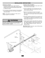
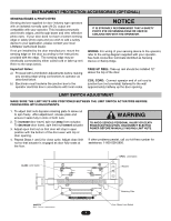
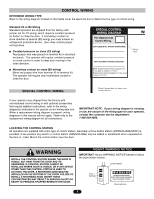
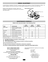
CONTROL WIRING (con't) Radio Controls On all models with type B2 control wiring, a terminal bracket marked R1 R2 R3 is located on the outside of the electrical enclosure. All standard radio control receivers (single channel residential type) may be mounted to this bracket. The operator will then open a fully closed door, close a fully open door, and reverse a closing door from the radio transmitter. However, for complete door control from a transmitter, a commercial three-channel radio set (with connections for OPEN/CLOSE/STOP) is recommended. WARNING DO NOT USE RADIO CONTROLS WITH YOUR OPERATOR UNLESS YOU HAVE INSTALLED SOME TYPE OF ENTRAPMENT PROTECTION DEVICE. THE USE OF RADIO CONTROLS PRESENTS POTENTIAL HAZARDS DUE TO THE USER'S ABILITY TO OPEN OR CLOSE THE DOOR WHEN OUT OF SIGHT OF THE DOOR. IN ADDITION, IF A SINGLE CHANNEL CONTROL IS USED, THE USER WILL NOT BE ABLE TO STOP THE DOOR FROM THE TRANSMITTER. Additional Access Control Equipment Locate any additional access control equipment as desired (but so that the door will be in clear sight of the person operating the equipment), and connect to the terminal block in the electrical enclosure as shown on the FIELD WIRING CONNECTIONS diagram. Any control with a normally (N.O.) isolated output contact may be connected in parallel with the OPEN button. More than one device may be connected in this manner. Use 16 gauge wire or larger for all controls. DO NOT USE THE CONTROL CIRCUIT TRANSFORMER (24VAC) IN THE OPERATOR TO POWER ANY ACCESS CONTROL EQUIPMENT OTHER THAN A STANDARD RESIDENTIAL TYPE RADIO RECEIVER. External Interlock Switch The operator has a terminal connection for an external interlock switch. This switch must be a normally closed (N.C.) two-wire device with a contact rating of at least 3 amps at 24VAC. When such a switch is connected as shown on the FIELD WIRING CONNECTIONS diagram, the control circuit will be disabled when the switch is actuated, thereby preventing electrical operation of the door from the control devices. CLUTCH ADJUSTMENT 1. Remove cotterpin from nut on the clutch shaft. 2. Back off clutch nut until there is very little tension on the clutch spring. 3. Tighten clutch nut gradually until there is just enough tension to permit the operator to move the door smoothly but to allow the clutch to slip if the door is obstructed. When the clutch is properly adjusted, it should generally be possible to stop the door by hand during travel. 4. Reinstall Cotterpin. CAUTION: The adjustable friction clutch is NOT an automatic reversing device. An electric or pneumatic reversing edge can be added to bottom edge of door if desired. Adjusting Nut Spring Clutch Pad Clutch Plate Cotterpin Washer Clutch Pulley 9
-
 1
1 -
2
-
3
-
 4
4 -
 5
5 -
 6
6 -
 7
7 -
 8
8 -
 9
9 -
 10
10 -
 11
11 -
 12
12 -
 13
13 -
 14
14 -
15
-
16
-
17
-
18
-
19
-
20
 |
 |