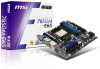
MSI 785GM User Guide - Page 28
Front Panel Connector: JFP1
 |
View all MSI 785GM manuals
Add to My Manuals
Save this manual to your list of manuals |
Page 28 highlights
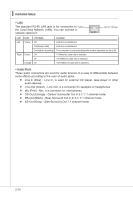
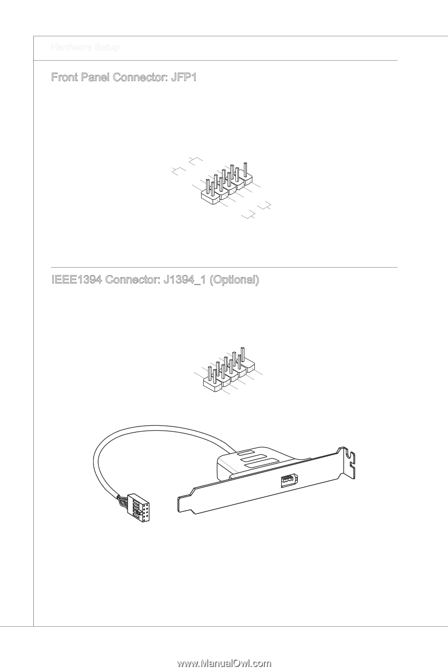
▍ Hardware Setup Front Panel Connector: JFP1 This connector is for electrical connection to the front panel switches and LEDs. The JFP1 is compliant with Intel® Front Panel I/O Connectivity Design Guide. PowPoewr LeEr DSwi2tc.h+41.0-6..N+8o.-Pin 1.+3.-5.-7.H+9D.RDReLseEesDrevteSdwitch IEEE1394 Connector: J1394_1 (Optional) This connector allows you to connect the IEEE1394 device via an optional IEEE1394 bracket. 2.T4P.GA6-.rTo8Pu1.+nB01d.-G2Vround 1 .T3P.G5A.r+To7Pu. +9nB1.d+N2oV P i n IEEE1394 Bracket (optional) 2-14
-
 1
1 -
2
-
3
-
4
-
5
-
6
-
7
-
8
-
9
-
10
-
11
-
12
-
13
-
14
-
15
-
16
-
17
-
18
-
19
-
20
-
21
-
22
-
 23
23 -
 24
24 -
 25
25 -
 26
26 -
 27
27 -
 28
28 -
 29
29 -
 30
30 -
 31
31 -
 32
32 -
 33
33 -
34
-
35
-
36
-
37
-
38
-
39
-
40
-
41
-
42
-
43
-
44
-
45
-
46
-
47
-
48
-
49
-
50
-
51
-
52
-
53
-
54
-
55
-
56
-
57
-
58
-
59
-
60
-
61
-
62
-
63
-
64
-
65
-
66
-
67
-
68
-
69
-
70
-
71
-
72
-
73
-
74
-
75
-
76
-
77
-
78
-
79
-
80
-
81
-
82
-
83
-
84
-
85
-
86
-
87
-
88
-
89
-
90
-
91
-
92
-
93
-
94
-
95
-
96
-
97
-
98
-
99
-
100
-
101
-
102
-
103
 |
 |
2-14
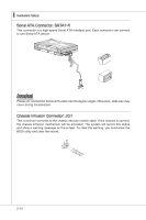
Hardware Setup
▍
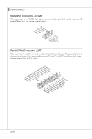
Front Panel Connector: JFP1
Th±s connector ±s for electr±cal connect±on to the front panel sw±tches and LEDs. The
JFP1 ±s compl±ant w±th Intel
®
Front Panel I/O Connect±v±ty Des±gn Gu±de.
1.+
3.-
10.No Pin
5.-
Reset Switch
HDD LED
Power Switch
Power LED
7.+
9.Reserved
8.-
6.+
4.-
2.+
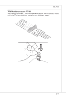
IEEE1394 Connector: J1394_1 (Opt±onal)
Th±s connector allows you to connect the IEEE1394 dev±ce v±a an opt±onal IEEE1394
bracket.
1.TPA+
3.Ground
10.Ground
5.TPB+
7.+12V
9.No Pin
8.+12V
6.TPB-
4.Ground
2.TPA-
IEEE1394 Bracket (opt±onal)