MSI 790GX User Guide - Page 26
Serial ATA Connector: SATA1~5, IEEE1394 Connector: J1394_1 Optional
 |
View all MSI 790GX manuals
Add to My Manuals
Save this manual to your list of manuals |
Page 26 highlights
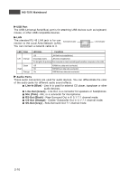
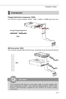
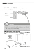
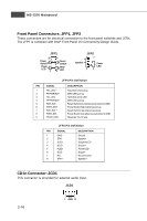
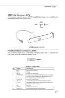
MS-7576 Mainboard Serial ATA Connector: SATA1~5 This connector is a high-speed Serial ATA interface port. Each connector can connect to one Serial ATA device. SATA1 SATA4_5 SATA2_3 Important 1. SATA5 only supports RAID and AHCI mode (does not support IDE mode) 2. Please do not fold the Serial ATA cable into 90-degree angle. Otherwise, data loss may occur during transmission. IEEE1394 Connector: J1394_1 (Optional) This connector allows you to connect the IEEE1394 device via an optional IEEE1394 bracket. Pin Definition 2 10 1 9 J1394_1 (optional) PIN SIGNAL PIN 1 TPA+ 2 3 Ground 4 5 TPB+ 6 7 Cable power 8 9 Key (no pin) 10 SIGNAL TPAGround TPBCable power Ground 2-12 IEEE1394 Bracket (Optional)
-
 1
1 -
2
-
3
-
4
-
5
-
6
-
7
-
8
-
9
-
10
-
11
-
12
-
13
-
14
-
15
-
16
-
17
-
18
-
19
-
20
-
 21
21 -
 22
22 -
 23
23 -
 24
24 -
 25
25 -
 26
26 -
 27
27 -
 28
28 -
 29
29 -
 30
30 -
 31
31 -
32
-
33
-
34
-
35
-
36
-
37
-
38
-
39
-
40
-
41
-
42
-
43
-
44
-
45
-
46
-
47
-
48
-
49
-
50
-
51
-
52
-
53
-
54
-
55
-
56
-
57
-
58
-
59
-
60
-
61
-
62
-
63
-
64
-
65
-
66
-
67
-
68
-
69
-
70
-
71
-
72
-
73
-
74
-
75
-
76
-
77
-
78
-
79
-
80
-
81
-
82
-
83
-
84
-
85
-
86
-
87
-
88
-
89
-
90
-
91
-
92
-
93
-
94
-
95
-
96
-
97
-
98
-
99
-
100
-
101
-
102
-
103
-
104
 |
 |

2-12
MS-7576 Mainboard
Serial ATA Connector: SATA1~5
This connector is a high-speed Serial ATA interface port. Each connector can con-
nect to one Serial ATA device.
SATA4_5
SATA1
Important
1. SATA5 only supports RAID and AHCI mode (does not support IDE mode)
2. Please do not fold the Serial ATA cable into 90-degree angle. Otherwise,
data loss may occur during transmission.
SATA2_3
IEEE1394 Connector: J1394_1 (Optional)
This connector allows you to connect the IEEE1394 device via an optional IEEE1394
bracket.
Pin Definition
PIN
SIGNAL
PIN
SIGNAL
1
TPA+
2
TPA-
3
Ground
4
Ground
5
TPB+
6
TPB-
7
Cable power
8
Cable power
9
Key (no pin)
10
Ground
IEEE1394 Bracket
(Optional)
J1394_1
(optional)
1
2
9
10