MSI 865PE NEO2-PLS User Guide - Page 33
Serial Port Connectors: COM A, VGA Connector Optional
 |
UPC - 816909004755
View all MSI 865PE NEO2-PLS manuals
Add to My Manuals
Save this manual to your list of manuals |
Page 33 highlights
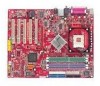
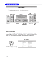
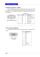
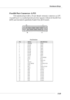
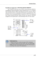
MS-6728 ATX Mainboard Serial Port Connectors: COM A The mainboard offers one 9-pin male DIN connectors as serial port COM A. The port is a 16550A high speed communication port that sends/receives16 bytes FIFOs. You can attach a serial mouse or other serial devices directly to the connectors. Pin Definition 1 2 3 4 5 PIN SIGNAL DESCRIPTION 1 2 3 4 6 7 8 9 5 9-Pin Male DIN Connector 6 7 8 9 DCD SIN SOUT DTR GND DSR RTS CTS RI Data Carry Detect Serial In or Receive Data Serial Out or Transmit Data Data Terminal Ready) Ground Data Set Ready Request To Send Clear To Send Ring Indicate VGA Connector (Optional) The mainboard provides a DB 15-pin female connector to connect a VGA monitor. 5 1 15 11 VGA Connector (DB 15-pin) Pin Signal Description 1 RED 2 GREEN 3 BLUE 4 N/C 5 GND 6 GND 7 GND 8 GND 9 +5V 10 GND 11 N/C 12 SDA 13 Horizontal Sync 14 Vertical Sync 15 SCL 2-12
-
 1
1 -
2
-
3
-
4
-
5
-
6
-
7
-
8
-
9
-
10
-
11
-
12
-
13
-
14
-
15
-
16
-
17
-
18
-
19
-
20
-
21
-
22
-
23
-
24
-
25
-
26
-
27
-
 28
28 -
 29
29 -
 30
30 -
 31
31 -
 32
32 -
 33
33 -
 34
34 -
 35
35 -
 36
36 -
 37
37 -
 38
38 -
39
-
40
-
41
-
42
-
43
-
44
-
45
-
46
-
47
-
48
-
49
-
50
-
51
-
52
-
53
-
54
-
55
-
56
-
57
-
58
-
59
-
60
-
61
-
62
-
63
-
64
-
65
-
66
-
67
-
68
-
69
-
70
-
71
-
72
-
73
-
74
-
75
-
76
-
77
-
78
-
79
-
80
-
81
-
82
-
83
-
84
-
85
-
86
-
87
-
88
-
89
-
90
-
91
-
92
-
93
-
94
-
95
-
96
-
97
-
98
-
99
-
100
-
101
-
102
-
103
-
104
-
105
-
106
-
107
-
108
-
109
-
110
-
111
-
112
-
113
-
114
-
115
-
116
-
117
-
118
 |
 |
