MSI 865PEM2 User Guide
MSI 865PEM2 Manual
 |
View all MSI 865PEM2 manuals
Add to My Manuals
Save this manual to your list of manuals |
MSI 865PEM2 manual content summary:
- MSI 865PEM2 | User Guide - Page 1
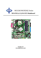
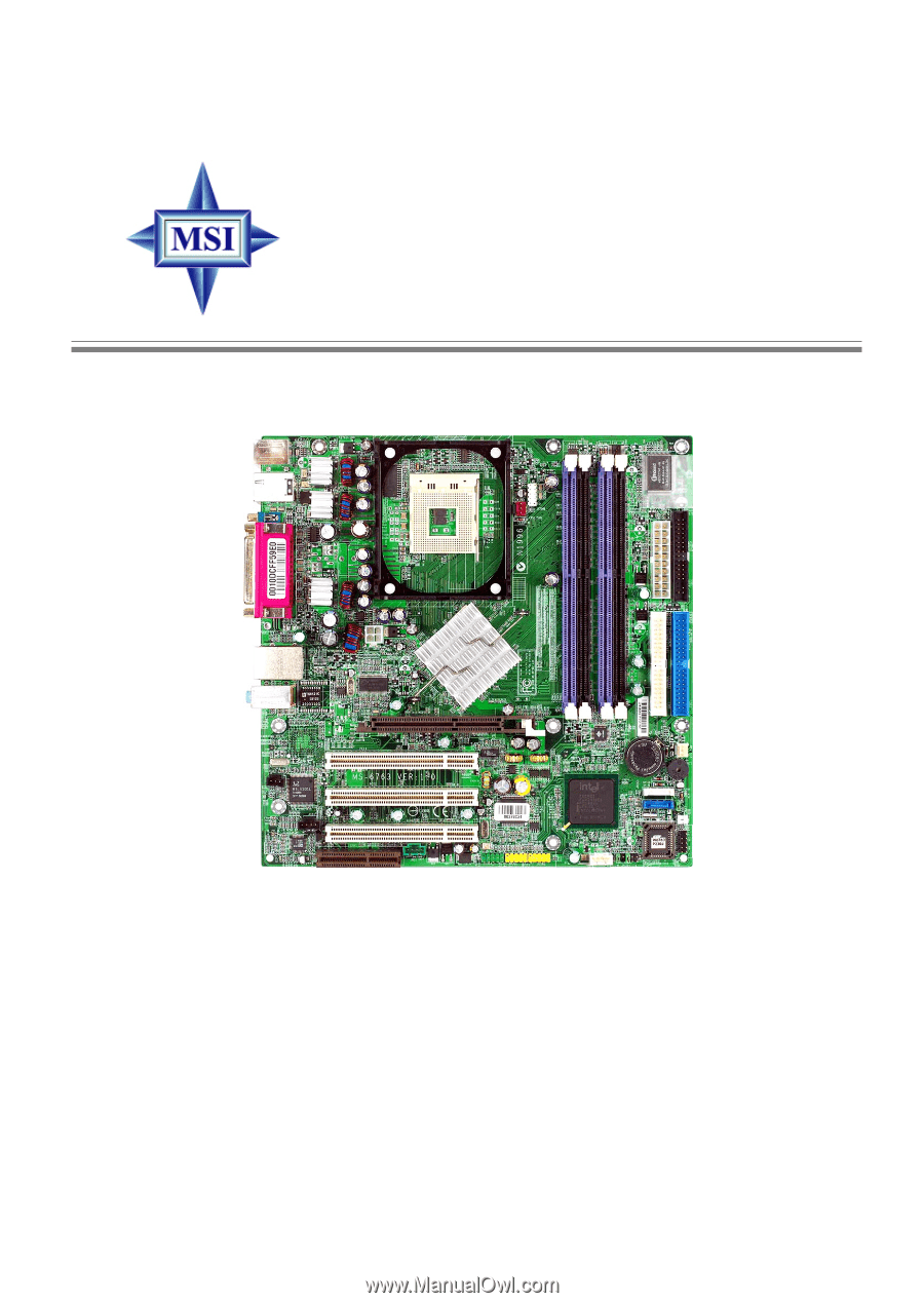
865GM3/865PEM2 Series MS-6763 (v1.X) M-ATX Mainboard Version 1.0 G52-M6763X1-G22 i - MSI 865PEM2 | User Guide - Page 2
Manual Rev: 1.0 Release Date: July 2003 FCC-B Radio Frequency Interference Statement This equipment radiate radio frequency energy and, if not installed and used in accordance with the instruction manual, may cause harmful interference to radio communications. Operation of this equipment in a - MSI 865PEM2 | User Guide - Page 3
/NT/XP are Support If a problem arises with your system and no solution can be obtained from the user's manual, please contact your place of purchase or local distributor. Alternatively, please try the following help resources for further guidance. Visit the MSI website for FAQ, technical guide, BIOS - MSI 865PEM2 | User Guide - Page 4
1. Always read the safety instructions carefully. 2. Keep this User's Manual for future reference. 3. Keep this equipment away shock. 11. If any of the following situations arises, get the equipment checked by a service personnel: z The power cord or plug is damaged. z Liquid has penetrated into the - MSI 865PEM2 | User Guide - Page 5
iii Copyright Notice iii Revision History iii Technical Support iii Safety Instructions iv Chapter 1. Getting Started 1-1 Mainboard Specifications 1-2 Mainboard Layout 1-4 Chapter 2. Hardware Setup 2-1 Quick Components Guide 2-2 Central Processing Unit: CPU 2-3 CPU Core Speed Derivation - MSI 865PEM2 | User Guide - Page 6
2-21 Front Panel Audio Connector: JAUD1 2-22 Front USB Connectors: JUSB1, JUSB2 2-23 IEEE 1394 Connector: J1394_1 (Optional for 865PEM2 Series) .... 2-24 BIOS Setup 3-1 Entering Setup 3-2 Control Keys 3-2 Getting Help 3-3 The Main Menu 3-4 Standard CMOS Features 3-6 Advanced BIOS Features - MSI 865PEM2 | User Guide - Page 7
Integrated Peripherals 3-15 Power Management Setup 3-21 PNP/PCI Configurations 3-25 PC Health Status 3-27 Frequency/Voltage Control 3-29 Load Default Setting 3-30 Set Supervisor/User Password 3-31 vii - MSI 865PEM2 | User Guide - Page 8
Getting Started Chapter 1. Getting Started Getting Started Thank you for choosing the 865GM3/865PEM2 Series (MS-6763 v1.X) micro ATX mainboard. The 865GM3/865PEM2 Series are based on Intel® Springdale-G/PE & ICH5 chipsets for optimal system efficiency. Designed to fit the advanced Intel® Pentium® 4 - MSI 865PEM2 | User Guide - Page 9
ATX Mainboard Mainboard Specifications CPU h Supports Intel® P4 Northwood (Socket 478) processors. h FSB 533~800MHz, depending on the CPU installed. h Supports up to 3.2GHz. Chipset h Intel® Springdale-PE/G chipset - Supports FSB 800/533/400MHz. - Supports AGP 8X/4X interface. - Supports DDR 400/333 - MSI 865PEM2 | User Guide - Page 10
Out via bracket only. LAN h Intel 82547EI (for 865GM3 Series only) - Integrated 10/100/1000Mbps Ethernet MAC and PHY in one chip. - Supports auto-negotiation operation. - Compliant with PCI v2.2, and LAN on Motherboard (LOM) standard. h RealTek RTL8101L (for 865PEM2 Series only) - Integrated 10 - MSI 865PEM2 | User Guide - Page 11
1 DIMM 2 DIMM 3 DIMM 4 IDE 2 IDE 1 PCI Slot 1 PCI Slot 2 PCI Slot 3 NEC D72874GC JMD1 J1394_1 JUSB1 B AT T + SYS_FAN ICH5 SATA2 SATA1 JBAT1 JCI1 JAUX1 JAUD1 BIOS JUSB2 JFP1 865PEM2 Series (MS-6763 v1.X) Micro ATX Mainboard 1-4 - MSI 865PEM2 | User Guide - Page 12
AGP Slot PCI Slot 1 PCI Slot 2 PCI Slot 3 JMD1 DIMM 1 DIMM 2 DIMM 3 DIMM 4 IDE 2 IDE 1 JUSB1 B AT T + SYS_FAN ICH5 SATA2 SATA1 JBAT1 JCI1 JAUX1 JAUD1 BIOS JUSB2 JFP1 865GM3 Series (MS-6763 v1.X) Micro ATX Mainboard 1-5 - MSI 865PEM2 | User Guide - Page 13
Hardware Setup Chapter 2. Hardware Setup Hardware Setup This chapter provides you with the information about hardware setup procedures. While doing the installation, be careful in holding the components and follow the installation procedures. For some components, if you install in the wrong - MSI 865PEM2 | User Guide - Page 14
MS-6763 M-ATX Mainboard Quick Components Guide DDR DIMMs, p.2-7 CPU_FAN, p.2-19 CPU, p.2-3 JCOM1, p.2-11 Back Panel I/O, p.2-10 JPW1, p.2-9 ATX1, p.2-9 FDD1, p.2-16 AGP1, p.2-26 JSP1, p.2-20 JCD1, p.2-20 CNR1, p.2-26 IDE2/1, p.2-17 SYS_FAN, p.2- - MSI 865PEM2 | User Guide - Page 15
Hardware Setup Central Processing Unit: CPU The mainboard supports Intel® Pentium® 4 processors in the 478 pin CPU core speed = Host Clock x Core/Bus ratio = 100MHz x 24 = 2.4 GHz MSI Reminds You... Overheating Overheating will seriously damage the CPU and system, always make sure the cooling - MSI 865PEM2 | User Guide - Page 16
MS-6763 M-ATX Mainboard CPU Installation Procedures for Socket 478 1. Please turn off the power and unplug the power cord before installing the CPU. 2. Pull the lever sideways away from the socket. Make sure to raise the lever up to a 90-degree angle. 3. Look for the gold arrow. The gold arrow - MSI 865PEM2 | User Guide - Page 17
need to attach the CPU cooling fan and heatsink on top of the CPU. Follow the instructions below to install the Heatsink/Fan: 1. Locate the CPU and its retention mechanism on the motherboard. retention mechanism 2. Position the heatsink onto the retention mechanism. 3. Mount the fan on top of the - MSI 865PEM2 | User Guide - Page 18
MS-6763 M-ATX Mainboard 5. Connect the fan power cable from the mounted fan to the 3-pin fan power connector on the board. fan power cable NOTES 2-6 - MSI 865PEM2 | User Guide - Page 19
the memory size up to 4GB. To operate properly, at least two DIMM modules must be installed onboard. Memory Speed/CPU FSB Support Matrix DDR DIMM Slots (DIMM 1~4) FSB400 FSB533 FSB800 DDR200 V V V DDR266 V V V DDR333 X V V DDR400 X X V DDR Population Rules Install at least one DIMM module on - MSI 865PEM2 | User Guide - Page 20
on the memory module is deeply inserted in the socket. 3. The plastic clip at each side of the DIMM slot will automatically close. Volt Notch MSI Reminds You... You can barely see the golden finger if the module is properly inserted in the socket. 2-8 - MSI 865PEM2 | User Guide - Page 21
Hardware Setup Power Supply The mainboard supports ATX power supply for the power system. Before inserting the power supply connector, always make sure that all components are installed properly to ensure that - MSI 865PEM2 | User Guide - Page 22
ATX Mainboard Back Panel The back panel provides the following connectors: 1394 Port Mouse (for 865PEM2) Parallel LAN L-In (Optional) Keyboard USB Ports COM A VGA Port USB Ports L-Out (for 865GM3) Mic-In Mouse/Keyboard Connector The mainboard provides a standard PS/2® mouse/keyboard mini DIN - MSI 865PEM2 | User Guide - Page 23
Receive Data Serial Out or Transmit Data Data Terminal Ready Ground Data Set Ready Request To Send Clear To Send Ring Indicate VGA Connector (for 865GM3 Series only) The mainboard provides a DB 15-pin female connector to connect a VGA monitor. 5 1 15 11 VGA Connector (DB 15-pin) Pin Signal - MSI 865PEM2 | User Guide - Page 24
Port Connector: LPT1 The mainboard provides a 25-pin female centronic connector as LPT. A parallel port is a standard printer port that supports Enhanced Parallel Port (EPP) and Extended Capabilities Parallel Port (ECP) mode. 13 1 25 14 Pin Definition PIN SIGNAL DESCRIPTION 1 STROBE - MSI 865PEM2 | User Guide - Page 25
) The mainboard provides one standard RJ-45 jack for connection to Local Area Network (LAN). Two LAN chipsets are available upon request: 1. 10/100Mbps LAN for 865PEM2-IL mainboard. 2. Gigabit LAN for 865GM3-F mainboard. Gigabit LAN enables data to be transferred at 1000, 100 or 10Mbps. 10/ 100 - MSI 865PEM2 | User Guide - Page 26
MS-6763 M-ATX Mainboard IEEE1394 Port (Optional for 865PEM2 Series only) The back panel provides one standard providing enhanced PC connectivity for a wide range of devices, including consumer electronics audio/video (A/V) appliances, storage peripherals, other PCs, and portable devices. IEEE1394 - MSI 865PEM2 | User Guide - Page 27
Hardware Setup Audio Port Connectors Line Out is a connector for Speakers or Headphones. Line In is used for external CD player, Tape player, or other audio devices. Mic is a connector for microphones. 1/8" Stereo Audio Connectors Line In Line Out Mic In 2-15 - MSI 865PEM2 | User Guide - Page 28
FDD, IDE HDD, case, audio, LAN, USB Ports, and CPU/System fans. Floppy Disk Drive Connector: FDD1 The mainboard provides a standard floppy disk drive connector that supports 360K, 720K, 1.2M, . To clear the warning, you must enter the BIOS setting and clear the status. 2-16 JCI1 GND CINTRU 1 - MSI 865PEM2 | User Guide - Page 29
disk drives, CD-ROM, 120MB Floppy (reserved for future BIOS) and other devices. These connectors support the provided IDE hard disk cable. IDE2 IDE1 IDE1 (Primary IDE Connector) IDE2 can also connect a Master and a Slave drive. MSI Reminds You... If you install two hard disks on cable, you must - MSI 865PEM2 | User Guide - Page 30
. The ports support 1st generation Serial ATA data rates of 150MB/s and are fully compliant with Serial ATA 1.0 specifications. Each Serial dust cover and connect to the hard disk devices Connect to SATA1 or SATA2 MSI Reminds You... Please do not fold the Serial ATA cable into 90-degree angle. Otherwise - MSI 865PEM2 | User Guide - Page 31
. It supports three-pin head connector. When connecting the wire to the connectors, always take note that the red wire is the positive and should be connected to the +12V, the black wire is Ground and should be connected to GND. GND +12V Sensor CPU_FAN GND +12V SENSOR SYS_FAN MSI Reminds You - MSI 865PEM2 | User Guide - Page 32
SPDIF-Out Connector: JSP1 (Optional) This connector is used to connect SPDIF (Sony & Philips Digital Interconnect Format) interface for digital audio transmission. JSP1 VCC GND SPDIF JCD1 R L GND Connected to JSP1 JMD1 JAUX1 GND R Mono_Out Phone_In L GND 2-20 SPDIF Bracket (Optional - MSI 865PEM2 | User Guide - Page 33
panel connector for electrical connection to the front panel switches and LEDs. The JFP1 is compliant with Intel® Front Panel I/O Connectivity Design Guide. JFP1 10 Power Switch Power LED 2 9 Reset Switch HDD 1 LED JFP1 Pin Definition PIN SIGNAL 1 HD_LED_P 2 FP PWR/SLP 3 HD_LED_N 4 FP - MSI 865PEM2 | User Guide - Page 34
front panel 7 NC No connection 8 KEY No pin 9 AUD_FPOUT_L Left channel audio signal to front panel 10 AUD_RET_L Left channel audio signal return from front panel MSI Reminds You... If you don't want to connect to the front audio header, pins 5 & 6, 9 & 10 have to be jumpered in order to - MSI 865PEM2 | User Guide - Page 35
Hardware Setup Front USB Connectors: JUSB1, JUSB2 The mainboard provides two USB 2.0 pin headers JUSB1/2 that are compliant with Intel® I/O Connectivity Design Guide. USB 2.0 technology increases data transfer rate up to a maximum throughput of 480Mbps, which is 40 times faster than USB 1.1, and is - MSI 865PEM2 | User Guide - Page 36
MS-6763 M-ATX Mainboard IEEE 1394 Connector: J1394_1 (Optional for 865PEM2 Series) The mainboard provides one 1394 pin header that allows you to connect IEEE 1394 ports via an external IEEE1394 bracket (optional). 9 1 10 2 J1394_1 Pin - MSI 865PEM2 | User Guide - Page 37
computer's function. This section will explain how to change your motherboard's function through the use of jumpers. Clear CMOS Jumper: JBAT1 CMOS Jumper ) to clear data. 1 JBAT1 1 1 3 Keep Data 3 Clear Data MSI Reminds You... You can clear CMOS by shorting 2-3 pin while the system is off. Then - MSI 865PEM2 | User Guide - Page 38
expansion card, such as jumpers, switches or BIOS configuration. CNR (Communication Network Riser) Slot The CNR slot allows you to insert the CNR expansion cards. CNR is a specially designed network, audio, or modem riser card for ATX family motherboards. Its main processing is done through software - MSI 865PEM2 | User Guide - Page 39
Hardware Setup PCI Interrupt Request Routing The IRQ, acronym of interrupt request line and pronounced I-R-Q, are hardware lines over which devices can send interrupt signals to the microprocessor. The PCI IRQ pins are typically connected to the PCI bus INT A# ~ INT D# pins as follows: PCI Slot 1 - MSI 865PEM2 | User Guide - Page 40
This chapter provides information on the BIOS Setup program and allows you to configure the system for optimum use. You may need to run the Setup program when: ” An error message appears - MSI 865PEM2 | User Guide - Page 41
MS-6763 M-ATX Mainboard Entering Setup Power on the computer and the system will start POST (Power On Self Test) process. When the message below appears on the screen, press key to enter Setup. Press DEL to enter SETUP If the message disappears before you respond and you still wish to enter - MSI 865PEM2 | User Guide - Page 42
the appropriate keys to use and the possible selections for the highlighted item. Press to exit the Help screen. MSI Reminds You... The items under each BIOS category described in this chapter are under continuous update for better system performance. Therefore, the description may be slightly - MSI 865PEM2 | User Guide - Page 43
press to enter the sub-menu. Standard CMOS Features Use this menu for basic system configurations, such as time, date etc. Advanced BIOS Features Use this menu to configure the special enhanced features. Advanced Chipset Features Use this menu to change the values in the chipset registers - MSI 865PEM2 | User Guide - Page 44
BIOS Setup PNP/PCI Configurations This entry appears if your system supports PnP/PCI. PC Health Status This menu shows for frequency/voltage control. Load Default Setting Use this menu to load the BIOS default values that are factory settings for optimal system operations. Set Supervisor/User - MSI 865PEM2 | User Guide - Page 45
. day Day of the week, from Sun to Sat, determined by BIOS. Read-only. month The month from Jan. through Dec. date The date from 1 to Press PgUp/ or PgDn/ to select Manual, None, Auto type. Note that the specifications of your drive must match with the drive table. The hard - MSI 865PEM2 | User Guide - Page 46
BIOS Setup will not work properly if you enter improper information for this category. If your hard disk drive type is not matched or listed, you can use Manual to define your own drive type manually. If you select Manual, related information is asked to be entered to the following items. Enter - MSI 865PEM2 | User Guide - Page 47
MS-6763 M-ATX Mainboard Advanced BIOS Features Hard Disk Boot Priority This setting determines the sector protection. If the function is enabled and any attempt to write data into this area is made, BIOS will display a warning message on screen and beep. Setting options: Disabled, Enabled. CPU L1 & - MSI 865PEM2 | User Guide - Page 48
MSI Reminds You... Enabling the functionality of Hyper-Threading Technology for your computer system requires ALL of the following platform Components: *CPU: An Intel® Pentium® 4 Processor with HT Technology; *Chipset: An Intel® Chipset that supports HT Technology; *BIOS: A BIOS that supports LS-120 - MSI 865PEM2 | User Guide - Page 49
the HDD at USB ports. LAN The system will boot from the and B:. Boot Up Floppy Seek Setting to Enabled will make BIOS seek floppy drive A: before booting the system. Setting options: the Gate A20 is controlled by Port92 or chipset specific method resulting in faster system performance. When Normal - MSI 865PEM2 | User Guide - Page 50
the type of BIOS password protection Advanced Programmable Interrupt Controller). Due to compliance with PC2001 design guide, the system is able to run in APIC mode. Enabling (Multi-Processor Specification) version to be used for the operating system. You need to select the MPS version supported by your - MSI 865PEM2 | User Guide - Page 51
) EEPROM on the DRAM module. Setting to By SPD enables DRAM timings to be determined by BIOS based on the configurations on the SPD. Selecting Manual allows users to configure the DRAM timings manually. CAS Latency Time This controls the timing delay (in clock cycles) before SDRAM starts a read - MSI 865PEM2 | User Guide - Page 52
. However, if any program writes to this memory area, a system error may result. Setting options: Enabled, Disabled. Video BIOS Cacheable Selecting Enabled allows caching of the video BIOS ROM at C0000h to C7FFFh, resulting in better video performance. However, if any program writes to this memory - MSI 865PEM2 | User Guide - Page 53
MS-6763 M-ATX Mainboard AGP Aperture Size (MB) This setting controls just how much system RAM can be allocated to AGP for video purposes. The aperture is a portion of the PCI memory address range dedicated to graphics memory address space. Host cycles that hit the aperture range are forwarded to the - MSI 865PEM2 | User Guide - Page 54
Integrated Peripherals BIOS Setup OnChip IDE Device Press to enter the sub-menu and the following screen appears: IDE HDD Block Mode Block mode is also called block transfer, multiple commands, or multiple sector read/write. If your IDE hard drive supports block mode (most new drives do), - MSI 865PEM2 | User Guide - Page 55
that do not support IDE drivers, ex: that the onboard IDE interface supports. Modes 0 through 4 driver (Windows 95 OSR2 or a third-party IDE bus master driver). If your hard drive and your system software both support Ultra DMA/33, Ultra DMA/ 66 and Ultra DMA/100, select Auto to enable BIOS support - MSI 865PEM2 | User Guide - Page 56
BIOS Setup Serial ATA Port 1/2 Mode When On-Chip Serial ATA is set to Legacy Mode, setting options will show as follows: 1. Primary Master => Serial ATA - MSI 865PEM2 | User Guide - Page 57
LAN XP/ME. Setting options: Disabled, Enabled. USB Keyboard/Mouse Support Set to Enabled if you need to use a USB mouse/keyboard in the operating system that does not support or have any USB keyboard/mouse driver installed, such as DOS and SCO Unix. AC97 Audio Auto allows the motherboard's BIOS - MSI 865PEM2 | User Guide - Page 58
BIOS Setup AC97 Modem Auto allows the mainboard to detect whether a modem is cards to connect a modem. Settings: Auto, Disabled. Onboard LAN Device (for 865PE) This setting is used to enable/disable the onboard 10/100Mbps LAN controller. Setting options: Disabled, Enabled. Onboard 1394 Device (for - MSI 865PEM2 | User Guide - Page 59
"EPP." By choosing "ECP", the onboard parallel port will operate in ECP mode only. Choosing "ECP + EPP" will allow the onboard parallel port to support both the ECP and EPP modes simultaneously. EPP Mode Select The onboard parallel port is EPP Spec. compliant, so after the user chooses the onboard - MSI 865PEM2 | User Guide - Page 60
Power Management Setup MSI Reminds You... S3-related functions described in this section are available only when your BIOS supports S3 sleep mode. ACPI Suspend Type This item specifies the power saving modes for ACPI function. If your operating system supports ACPI, such as Windows 98SE, Windows - MSI 865PEM2 | User Guide - Page 61
] allows BIOS to call VGABIOS to initialize the VGA card when system wakes up (resumes) from S3 sleep state. The system resume time is shortened when you disable the function, but system will need an AGP driver to initialize the VGA card. Therefore, if the AGP driver of the card does not support the - MSI 865PEM2 | User Guide - Page 62
BIOS Setup Suspend Mode If system activity is not detected for the length of time specified in this field, all devices except CPU will be shut - MSI 865PEM2 | User Guide - Page 63
MS-6763 M-ATX Mainboard MSI Reminds You... If you have changed this setting, you must let the system boot up until it enters the operating system, before this function will - MSI 865PEM2 | User Guide - Page 64
changes to the default settings. PNP OS Installed When set to Yes, BIOS will only initialize the PnP cards used for booting (VGA, IDE, SCSI be initialized by the PnP operating system like Windows 98. When set to No, BIOS will initialize all the PnP cards. So, select Yes if your operating system is - MSI 865PEM2 | User Guide - Page 65
Play operating system such as Windows® 95/98. If you set this field to "manual" choose specific resources by going into each of the sub menu that follows this field (a sub menu 7, 9, 10, 11, 12, 14, 15, Auto. Selecting Auto allows BIOS to automatically determine the IRQ line for each PCI slot. 3-26 - MSI 865PEM2 | User Guide - Page 66
BIOS Setup PC Health Status This section shows the status of your CPU, fan, limit preset in this setting, the warning mechanism will be activated. This helps you to prevent the CPU overheat problem. Current System/CPU Temp, Current CPU/System Fan Speed, Vcore(V), VTT(V), Vcc3(V), +5V, +12V, -12V - MSI 865PEM2 | User Guide - Page 67
MS-6763 M-ATX Mainboard Warning Beep This setting allows you to monitor the operation of the CPU fan. Setting to Enabled will activate the warning beep once the system detects the malfunction/halt of the CPU fan. 3-28 - MSI 865PEM2 | User Guide - Page 68
BIOS Setup Setting options: Enabled, Disabled. Spread Spectrum When the motherboard's clock generator pulses, the extreme values (spikes) the pulses are reduced to flatter curves. If you do not have any EMI problem, leave the setting at Disabled for optimal system stability and performance. But if - MSI 865PEM2 | User Guide - Page 69
MS-6763 M-ATX Mainboard Load Default Setting The Default Setting is the default values set by the mainboard manufacturer specifically for optimal performance of the mainboard. When you select Load Default Setting, a message as below appears: Pressing Y loads the default factory settings for optimal - MSI 865PEM2 | User Guide - Page 70
the password prompt is required is the Security Option of the ADVANCED BIOS FEATURES menu. If the Security Option is set to System, the to Setup, password prompt only occurs when you try to enter Setup. MSI Reminds You... About Supervisor Password & User Password: Supervisor password: Can
-
 1
1 -
 2
2 -
 3
3 -
 4
4 -
 5
5 -
 6
6 -
 7
7 -
8
-
9
-
10
-
11
-
12
-
13
-
14
-
15
-
16
-
17
-
18
-
19
-
20
-
21
-
22
-
23
-
24
-
25
-
26
-
27
-
28
-
29
-
30
-
31
-
32
-
33
-
34
-
35
-
36
-
37
-
38
-
39
-
40
-
41
-
42
-
43
-
44
-
45
-
46
-
47
-
48
-
49
-
50
-
51
-
52
-
53
-
54
-
55
-
56
-
57
-
58
-
59
-
60
-
61
-
62
-
63
-
64
-
65
-
66
-
67
-
68
-
69
-
70
 |
 |
Version 1.0
G52-M6763X1-G22
MS-6763 (v1.X) M-ATX Mainboard
865GM3/865PEM2 Series