MSI 865PEM2 User Guide - Page 65
IRQ Resources, PCI/VGA Palette Snoop, INT Pin 1~8 Assignment, Action
 |
View all MSI 865PEM2 manuals
Add to My Manuals
Save this manual to your list of manuals |
Page 65 highlights
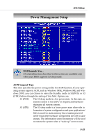
MS-6763 M-ATX Mainboard all of the boot and Plug and Play compatible devices. However, this capability means absolutely nothing unless you are using a Plug and Play operating system such as Windows® 95/98. If you set this field to "manual" choose specific resources by going into each of the sub menu that follows this field (a sub menu is preceded by a "¾"). Setting options: Auto (ESCD), Manual. IRQ Resources The items are adjustable only when Resources Controlled By is set to Manual. Press and you will enter the sub-menu of the items. IRQ Resources list IRQ 3/4/5/7/9/10/11/12/14/15 for users to set each IRQ a type depending on the type of device using the IRQ. Settings are: PCI Device Reserved For Plug & Play compatible devices designed for PCI bus architecture. The IRQ will be reserved for further request. PCI/VGA Palette Snoop When set to Enabled, multiple VGA devices operating on different buses can handle data from the CPU on each set of palette registers on every video device. Bit 5 of the command register in the PCI device configuration space is the VGA Palette Snoop bit (0 is disabled). For example, if there are two VGA devices in the computer (one PCI and one ISA): VGA Palette Snoop Bit Setting Action Disabled Data read or written by the CPU is only directed to the PCI VGA device's palette registers. Enabled Data read or written by the CPU is directed to both the PCI VGA device's palette registers and the ISA VGA device's palette registers, permitting the palette registers of both VGA devices to be identical. The setting must be set to Enabled if any ISA bus adapter in the system requires VGA palette snooping. INT Pin 1~8 Assignment These items specify the IRQ line for each PCI slot. Settings: 3, 4, 5, 7, 9, 10, 11, 12, 14, 15, Auto. Selecting Auto allows BIOS to automatically determine the IRQ line for each PCI slot. 3-26
-
 1
1 -
2
-
3
-
4
-
5
-
6
-
7
-
8
-
9
-
10
-
11
-
12
-
13
-
14
-
15
-
16
-
17
-
18
-
19
-
20
-
21
-
22
-
23
-
24
-
25
-
26
-
27
-
28
-
29
-
30
-
31
-
32
-
33
-
34
-
35
-
36
-
37
-
38
-
39
-
40
-
41
-
42
-
43
-
44
-
45
-
46
-
47
-
48
-
49
-
50
-
51
-
52
-
53
-
54
-
55
-
56
-
57
-
58
-
59
-
 60
60 -
 61
61 -
 62
62 -
 63
63 -
 64
64 -
 65
65 -
 66
66 -
 67
67 -
 68
68 -
 69
69 -
 70
70
 |
 |
