MSI 945GM3-F User Guide - Page 32
Front Panel Audio Connector: JAUD1, SPDIF-Out Connector: JSPD1 Optional
 |
UPC - 816909037449
View all MSI 945GM3-F manuals
Add to My Manuals
Save this manual to your list of manuals |
Page 32 highlights
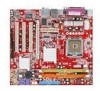
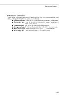
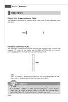
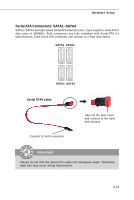
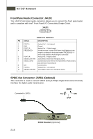
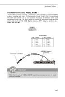
MS-7267 Mainboard Front Panel Audio Connector: JAUD1 The JAUD1 front panel audio connector allows you to connect the front panel audio and is compliant with Intel® Front Panel I/O Connectivity Design Guide. JAUD1 2 10 1 9 JAUD1 Pin Definition PIN SIGNAL DESCRIPTION 1 PORT 1L Analog Port 1 - Left channel 2 GND Ground 3 PORT 1R Analog Port 1 - Right channel 4 PRESENCE# Active low signal - signals BIOS that a High Definition Audio dongle is connected to the analog header. PRESENCE# = 0 when a High Definition Audio dongle is connected. 5 PORT 2R Analog Port 2 - Right channel 6 SENSE1_RETIRN Jack detection return from front panel JACK1 7 SENSE_SEND Jack detection sense line from the High Definition Audio CODEC jack detection resistor network 8 KEY Connector Key 9 PORT 2L Analog Port 2 - Left channel 10 SENSE2_RETIRN Jack detection return from front panel JACK2 SPDIF-Out Connector: JSPD1 (Optional) This connector is used to connect SPDIF (Sony & Philips Digital Interconnect Format) interface for digital audio transmission. Connected to JSPD1 JSPD1 VCC GND SPDIF 2-16 SPDIF Bracket (Optional)
-
 1
1 -
2
-
3
-
4
-
5
-
6
-
7
-
8
-
9
-
10
-
11
-
12
-
13
-
14
-
15
-
16
-
17
-
18
-
19
-
20
-
21
-
22
-
23
-
24
-
25
-
26
-
 27
27 -
 28
28 -
 29
29 -
 30
30 -
 31
31 -
 32
32 -
 33
33 -
 34
34 -
 35
35 -
 36
36 -
 37
37 -
38
-
39
-
40
-
41
-
42
-
43
-
44
-
45
-
46
-
47
-
48
-
49
-
50
-
51
-
52
-
53
-
54
-
55
-
56
-
57
-
58
-
59
-
60
-
61
-
62
-
63
-
64
-
65
-
66
-
67
-
68
-
69
-
70
-
71
-
72
-
73
-
74
-
75
-
76
-
77
-
78
-
79
-
80
-
81
-
82
 |
 |