MSI 990XA User Guide - Page 49
MS-7640, command starts., cell., for each channel., tRWTT02/ tWRRD2/ tWRWR2/ tRDRD2, DCT Unganged
 |
View all MSI 990XA manuals
Add to My Manuals
Save this manual to your list of manuals |
Page 49 highlights
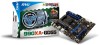
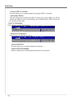
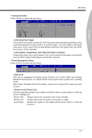
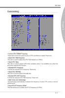
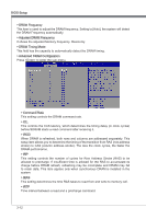
Chapter 3 MS-7640 ▶ tRC The row cycle time determines the minimum number of clock cycles a memory row takes to complete a full cycle, from row activation up to the precharging of the active row. ▶ tWR Minimum time interval between end of write data burst and the start of a precharge command. Allows sense amplifiers to restore data to cells. ▶ tRRD Specifies the active-to-active delay of different banks. ▶ tWTR Minimum time interval between the end of write data burst and the start of a columnread command. It allows I/O gating to overdrive sense amplifiers before read command starts. ▶ tRFC This setting determines the time RFC takes to read from and write to a memory cell. ▶ Advanced Channel 1/ 2 Timing Configuration Press to enter the sub-menu. And you can set the advanced memory timing for each channel. ▶ tRWTT02/ tWRRD2/ tWRWR2/ tRDRD2 These items is used to set the memory timings for memory channel 1/ 2. ▶ DCT Unganged Mode This feature is used to Integrate two 64-bit DCTs into a 128-bit interface. ▶ Bank Interleaving Bank Interleaving is an important parameter for improving overclocking capability of memory. It allows system to access multiple banks simultaneously. ▶ HT Link Speed This item allows you to set the Hyper-Transport Link speed. Setting to [Auto], the system will detect the HT link speed automatically. ▶ Adjusted HT Link Frequency It shows the adjusted HT Link frequency. Read-only. ▶ CPU Core Control This item allows you to select the number of active processor cores. ▶ Unlock CPU Core This item is used to unlock the CPU core. Please refer to the procedures below for CPU core unlocked in BIOS setup. 3-13
-
 1
1 -
2
-
3
-
4
-
5
-
6
-
7
-
8
-
9
-
10
-
11
-
12
-
13
-
14
-
15
-
16
-
17
-
18
-
19
-
20
-
21
-
22
-
23
-
24
-
25
-
26
-
27
-
28
-
29
-
30
-
31
-
32
-
33
-
34
-
35
-
36
-
37
-
38
-
39
-
40
-
41
-
42
-
43
-
 44
44 -
 45
45 -
 46
46 -
 47
47 -
 48
48 -
 49
49 -
 50
50 -
 51
51 -
 52
52 -
 53
53 -
 54
54 -
55
-
56
-
57
-
58
-
59
-
60
-
61
-
62
-
63
-
64
-
65
-
66
-
67
-
68
-
69
-
70
-
71
-
72
-
73
-
74
 |
 |
