MSI B350 PC MATE User Manual - Page 32
JCI1: Chassis Intrusion Connector, JLPT1: Parallel Port Connector
 |
View all MSI B350 PC MATE manuals
Add to My Manuals
Save this manual to your list of manuals |
Page 32 highlights
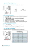
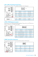
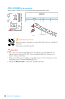
JCI1: Chassis Intrusion Connector This connector allows you to connect the chassis intrusion switch cable. Normal (default) Trigger the chassis intrusion event Using chassis intrusion detector 1. Connect the JCI1 connector to the chassis intrusion switch/ sensor on the chassis. 2. Close the chassis cover. 3. Go to BIOS > SETTINGS > Security > Chassis Intrusion Configuration. 4. Set Chassis Intrusion to Enabled. 5. Press F10 to save and exit and then press the Enter key to select Yes. 6. Once the chassis cover is opened again, a warning message will be displayed on screen when the computer is turned on. Resetting the chassis intrusion warning 1. Go to BIOS > SETTINGS > Security > Chassis Intrusion Configuration. 2. Set Chassis Intrusion to Reset. 3. Press F10 to save and exit and then press the Enter key to select Yes. JLPT1: Parallel Port Connector This connector allows you to connect the optional parallel port with bracket. 2 26 1 25 1 RSTB# 2 AFD# 3 PRND0 4 ERR# 5 PRND1 6 PINIT# 7 PRND2 8 LPT_SLIN# 9 PRND3 10 Ground 11 PRND4 12 Ground 13 PRND5 14 Ground 15 PRND6 16 Ground 17 PRND7 18 Ground 19 ACK# 20 Ground 21 BUSY 22 Ground 23 PE 24 Ground 25 SLCT 26 No Pin 32 Overview of Components
-
 1
1 -
2
-
3
-
4
-
5
-
6
-
7
-
8
-
9
-
10
-
11
-
12
-
13
-
14
-
15
-
16
-
17
-
18
-
19
-
20
-
21
-
22
-
23
-
24
-
25
-
26
-
 27
27 -
 28
28 -
 29
29 -
 30
30 -
 31
31 -
 32
32 -
 33
33 -
 34
34 -
 35
35 -
 36
36 -
 37
37 -
38
-
39
-
40
-
41
-
42
-
43
-
44
-
45
-
46
-
47
-
48
-
49
-
50
-
51
-
52
-
53
-
54
-
55
-
56
-
57
-
58
-
59
-
60
-
61
-
62
-
63
-
64
-
65
-
66
-
67
-
68
-
69
-
70
-
71
-
72
-
73
 |
 |
