MSI MEG Z390 ACE User Manual - Page 35
JFP1, JFP2: Front Panel Connectors, OC1: GAME BOOST Knob
 |
View all MSI MEG Z390 ACE manuals
Add to My Manuals
Save this manual to your list of manuals |
Page 35 highlights
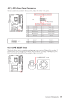
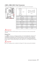
JFP1, JFP2: Front Panel Connectors These connectors connect to the switches and LEDs on the front panel. Power LED Power Switch - -+ -- ++ JFP1 2 1 + 10 9 Reserved HDD LED Reset Switch 1 HDD LED + 2 3 HDD LED - 4 5 Reset Switch 6 7 Reset Switch 8 9 Reserved 10 Power LED + Power LED Power Switch Power Switch No Pin 1 JFP2 1 Speaker - 2 3 Buzzer - 4 Buzzer + Speaker + OC1: GAME BOOST Knob This knob allows you to manually select a stage from number 0 (default) to number 11 (extreme) for overclocking the processor. The processor's voltage and frequency will be automatically adjusted after you power on your computer. GAME BOOST knob 0 1 8 10 1 2 1 6 4 Overview of Components 35
-
 1
1 -
2
-
3
-
4
-
5
-
6
-
7
-
8
-
9
-
10
-
11
-
12
-
13
-
14
-
15
-
16
-
17
-
18
-
19
-
20
-
21
-
22
-
23
-
24
-
25
-
26
-
27
-
28
-
29
-
 30
30 -
 31
31 -
 32
32 -
 33
33 -
 34
34 -
 35
35 -
 36
36 -
 37
37 -
 38
38 -
 39
39 -
 40
40 -
41
-
42
-
43
-
44
-
45
-
46
-
47
-
48
-
49
-
50
-
51
-
52
-
53
-
54
-
55
-
56
-
57
-
58
-
59
-
60
-
61
-
62
-
63
-
64
-
65
-
66
-
67
-
68
-
69
-
70
-
71
-
72
-
73
-
74
-
75
-
76
-
77
-
78
-
79
-
80
-
81
-
82
-
83
-
84
-
85
-
86
-
87
-
88
-
89
-
90
-
91
-
92
-
93
-
94
-
95
-
96
 |
 |

35
Overview of Components
JFP1, JFP2: Front Panel Connectors
These connectors connect to the switches and LEDs on the front panel.
1
2
10
9
+
+
+
-
-
-
-
+
Power LED
HDD LED
Reset Switch
Reserved
Power Switch
JFP1
1
HDD LED +
2
Power LED +
3
HDD LED -
4
Power LED -
5
Reset Switch
6
Power Switch
7
Reset Switch
8
Power Switch
9
Reserved
10
No Pin
1
JFP2
1
Speaker -
2
Buzzer +
3
Buzzer -
4
Speaker +
GAME BOOST knob
0
1
2
4
6
8
1
0
1
1
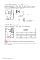
OC1: GAME BOOST Knob
This knob allows you to manually select a stage from number 0 (default) to number 11
(extreme) for overclocking the processor. The processor
’
s voltage and frequency will
be automatically adjusted after you power on your computer.