MSI MEG Z390 ACE User Manual - Page 38
CPU_PWR1~2, ATX_PWR1: Power Connectors, V-Check Points
 |
View all MSI MEG Z390 ACE manuals
Add to My Manuals
Save this manual to your list of manuals |
Page 38 highlights
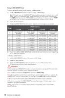
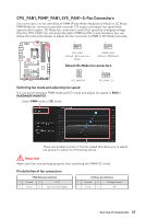
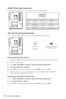
CPU_PWR1~2, ATX_PWR1: Power Connectors These connectors allow you to connect an ATX power supply. 8 5 CPU_PWR1/ CPU_PWR2 4 1 1 Ground 5 2 Ground 6 3 Ground 7 4 Ground 8 +12V +12V +12V +12V 1 +3.3V 13 2 +3.3V 14 3 Ground 15 12 24 4 +5V 16 5 Ground 17 6 +5V 18 ATX_PWR1 7 Ground 19 8 PWR OK 20 1 13 9 5VSB 21 10 +12V 22 11 +12V 23 12 +3.3V 24 +3.3V -12V Ground PS-ON# Ground Ground Ground Res +5V +5V +5V Ground Important Make sure that all the power cables are securely connected to a proper ATX power supply to ensure stable operation of the motherboard. V-Check Points These voltage checkpoints are used to measure the current system voltages. A multimeter (not included) will be required to check voltages. To measure voltage, place test leads on the GND (screw mounting hole) and a V-Check Point. Please refer to the manual of your multimeter for more information. PCH VCCIO VCCSA DDR CPU 38 Overview of Components
-
 1
1 -
2
-
3
-
4
-
5
-
6
-
7
-
8
-
9
-
10
-
11
-
12
-
13
-
14
-
15
-
16
-
17
-
18
-
19
-
20
-
21
-
22
-
23
-
24
-
25
-
26
-
27
-
28
-
29
-
30
-
31
-
32
-
 33
33 -
 34
34 -
 35
35 -
 36
36 -
 37
37 -
 38
38 -
 39
39 -
 40
40 -
 41
41 -
 42
42 -
 43
43 -
44
-
45
-
46
-
47
-
48
-
49
-
50
-
51
-
52
-
53
-
54
-
55
-
56
-
57
-
58
-
59
-
60
-
61
-
62
-
63
-
64
-
65
-
66
-
67
-
68
-
69
-
70
-
71
-
72
-
73
-
74
-
75
-
76
-
77
-
78
-
79
-
80
-
81
-
82
-
83
-
84
-
85
-
86
-
87
-
88
-
89
-
90
-
91
-
92
-
93
-
94
-
95
-
96
 |
 |
