MSI MEG Z790 ACE MAX User Manual 1
MSI MEG Z790 ACE MAX Manual
 |
View all MSI MEG Z790 ACE MAX manuals
Add to My Manuals
Save this manual to your list of manuals |
MSI MEG Z790 ACE MAX manual content summary:
- MSI MEG Z790 ACE MAX | User Manual 1 - Page 1
MEG Series Motherboard MEG Z790 ACE MAX User Guide - MSI MEG Z790 ACE MAX | User Manual 1 - Page 2
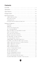
Contents Quick Start...4 Specifications...16 Special Features...22 Package Contents...23 Back Panel Connectors 24 LAN Port LED Status Table 25 Audio Jacks Connection 26 Installing Antennas 28 Connecting Thunderbolt Devices via Daisy-chain 29 Overview of Components 30 CPU Socket...31 DIMM Slots - MSI MEG Z790 ACE MAX | User Manual 1 - Page 3
...60 EZ Debug LED...60 LED_SW1: EZ LED Control 60 Debug Code LED...61 Boot Phases...61 Debug Code LED Table 61 Installing OS, Drivers & MSI Center 68 MSI Center...71 UEFI BIOS...72 BIOS Setup...73 Resetting BIOS...74 Updating BIOS...74 Block Diagram...76 Regulatory Notices...i 3 - MSI MEG Z790 ACE MAX | User Manual 1 - Page 4
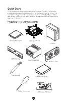
Quick Start Thank you for purchasing a new motherboard from MSI®. This Quick Start section provides demonstration diagrams about how to install your computer. Some of the installations also provide video demonstrations. Please link to the - MSI MEG Z790 ACE MAX | User Manual 1 - Page 5
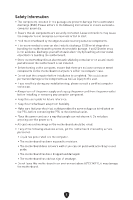
adhere to the following instructions to ensure successful motherboard checked by service personnel: • Liquid has penetrated into the computer. • The motherboard has been exposed to moisture. • The motherboard does not work well or you can not get it work according to user guide. • The motherboard - MSI MEG Z790 ACE MAX | User Manual 1 - Page 6
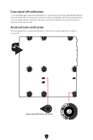
circuits and the computer case is prohibited. The Case standoff keep out zone signs will be marked on the backside of motherboard (as shown below) to serve as a warning to user. Avoid collision notification Protective paint is printed around each screw hole to prevent parts from being - MSI MEG Z790 ACE MAX | User Manual 1 - Page 7
Installing a Processor ⚽ 1 ∙ https://youtu.be/KMf9oIDsGes 2 7 5 4 6 3 9 8 7 - MSI MEG Z790 ACE MAX | User Manual 1 - Page 8
Installing DDR5 memory ⚽ ∙ https://youtu.be/XiNmkDNZcZk DIMMA2 DIMMA2 DIMMB2 8 DIMMA1 DIMMA2 DIMMB1 DIMMB2 - MSI MEG Z790 ACE MAX | User Manual 1 - Page 9
Connecting the Front Panel Header ⚽ ∙ http://youtu.be/DPELIdVNZUI POPWOEWRELREHLDD-EDDL+ED RESET SW POWER SW HDD LED RESET SW Power LED Power Switch JFP1 2 1 HDD LED 10 9 Reserved Reset Switch JFP1 HDD LED POWER LED 9 HDD LED HDD LED + POWER LED POWER LED + - MSI MEG Z790 ACE MAX | User Manual 1 - Page 10
Installing the Motherboard ⚽ 1 ∙ https://youtu.be/wWI6Qt51Wnc Torque: 3 kgf·cm* 2 *3 kgf·cm = 0.3 N·m = 2.6 lbf·in BAT1 10 - MSI MEG Z790 ACE MAX | User Manual 1 - Page 11
Connecting the Power Connectors ⚽ ∙ http://youtu.be/gkDYyR_83I4 ATX_PWR1 PD_PWR1 11 CPU_PWR1~2 - MSI MEG Z790 ACE MAX | User Manual 1 - Page 12
Installing SATA Drives ⚽ ∙ http://youtu.be/RZsMpqxythc 1 2 3 5 4 12 - MSI MEG Z790 ACE MAX | User Manual 1 - Page 13
Installing a Graphics Card ⚽ ∙ http://youtu.be/mG0GZpr9w_A 1 3 2 5 4 6 13 - MSI MEG Z790 ACE MAX | User Manual 1 - Page 14
Connecting Peripheral Devices 14 - MSI MEG Z790 ACE MAX | User Manual 1 - Page 15
Power On 1 2 3 4 15 - MSI MEG Z790 ACE MAX | User Manual 1 - Page 16
∙ Processor socket LGA1700 * Please go to www.msi.com to get the newest support status as new processors are released. Intel® Z790 Chipset ∙ 4x DDR5 memory slots, support up to 192GB* ∙ Supports 1R 5600 MHz (by JEDEC & POR) ∙ Max. overclocking frequency: • 1DPC 1R Max speed up to 7800+ MHz • 1DPC 2R - MSI MEG Z790 ACE MAX | User Manual 1 - Page 17
devices or five Thunderbolt 3 devices • Supports up to 8K display (need to connect the DisplayPort of the motherboard or discrete graphics card to the Mini DisplayPort Input port on the back panel) ∙ 6x SATA 6Gb/s ports • SATA_5~8* (From Z790 - MSI MEG Z790 ACE MAX | User Manual 1 - Page 18
• M2_3 slot (From Z790 chipset) • Supports up to PCIe 4.0 x4 • Supports up to SATA 6Gb/s • Supports 2260/ 2280 storage devices • M2_4 slot* (From CPU) • Supports up to PCIe 5.0 x4 • Supports 2280 storage devices • M2_5 slot** (From Z790 chipset) • Supports up to PCIe 4.0 x4 • Supports up to SATA 6Gb - MSI MEG Z790 ACE MAX | User Manual 1 - Page 19
. Internal USB Connectors ∙ 2x USB 3.2 Gen 2x2 20Gbps Type-C front panel connectors* (From Z790 chipset) • JUSB6 supports USB PD 60W fast charging ∙ 2x USB 3.2 Gen 1 5Gbps connectors (From Hub GL3523) • Supports additional 4 USB 3.2 Gen 1 5Gbps ports ∙ 2x USB 2.0 Type-A connectors (From Hub GL850G - MSI MEG Z790 ACE MAX | User Manual 1 - Page 20
chipset) ∙ 4x USB 3.2 Gen 2 10Gbps Type-A ports (From Hub- GL3590) ∙ 1x USB 3.2 Gen 2 10Gbps Type-C port (From Z790 chipset) with DisplayPort Alt Mode ∙ 2x Thunderbolt 4 USB-C ports ∙ 2x Mini DisplayPort Inputs (for Thunderbolt 4 pass through) ∙ 2x Wi-Fi Antenna connectors ∙ 5x OFC audio - MSI MEG Z790 ACE MAX | User Manual 1 - Page 21
in. (277 mm x 305 mm) ∙ Dual BIOS ∙ 2x 256 Mb flash ∙ UEFI AMI BIOS ∙ ACPI 6.4, SMBIOS 3.5 ∙ Multi-language ∙ Drivers ∙ MSI Center ∙ Intel Extreme Tuning Utility ∙ CPU-Z MSI GAMING ∙ Norton 360 ∙ 7-ZIP ∙ AIDA64 Extreme - MSI Edition ∙ MSI APP Player (BlueStacks) ∙ Adobe Creative Cloud ∙ Acrobat 21 - MSI MEG Z790 ACE MAX | User Manual 1 - Page 22
Special Features MSI Center Features • Gaming Mode • Smart Priority • Game Highlights • Mystic Light • PCI-E / M.2 Slot • Lightning Gen 4 PCI-E / M.2 Slot • USB4 • Lightning USB 20G • Multi GPU Support • Thunderbolt 4 • Front USB Type-C • USB with PD • Server Grade PCB • 2oz Copper thickened PCB DIY - MSI MEG Z790 ACE MAX | User Manual 1 - Page 23
check the contents of your motherboard package. It should contain: Board • 1x Motherboard Documentation • 1x Quick installation guide • 1x European Union regulatory drivers, please refer to Installing OS, Drivers & MSI Center chapter. ∙ If any of the above items are damaged or missing, please contact - MSI MEG Z790 ACE MAX | User Manual 1 - Page 24
2 2.5 Gbps LAN ports 3 USB 3.2 Gen 2 10Gbps Type-A ports (From Z790 chipset) 4 Wi-Fi antenna connectors 5 Audio jacks 6 Flash BIOS button - 4 functions for the smart button to achieve. Please refer to the BIOS manual for details about selecting the smart button function. ∙ Reset (default) - - MSI MEG Z790 ACE MAX | User Manual 1 - Page 25
chipset) 8 ∙ DisplayPort Alt Mode USB 3.2 Gen 2 10Gbps Type-A port (From Z790 chipset) 9 ∙ Flash BIOS port 10 USB 3.2 Gen 2 10Gbps Type-A ports (From Hub-GL3590) Thunderbolt 4 USB-C ports (From JHL8540) ∙ DisplayPort Alt Mode 11 ∙ USB4 20Gbps ∙ Power - MSI MEG Z790 ACE MAX | User Manual 1 - Page 26
Audio Jacks Connection Audio jacks to headphone and microphone diagram Audio jacks to stereo speakers diagram AUDIO INPUT 26 - MSI MEG Z790 ACE MAX | User Manual 1 - Page 27
Audio jacks to 4-channel speakers diagram AUDIO INPUT Rear Front Audio jacks to 5.1-channel speakers diagram AUDIO INPUT Rear Front Center/ Subwoofer Audio jacks to 7.1-channel speakers diagram AUDIO INPUT Rear Front Side Center/ Subwoofer 27 - MSI MEG Z790 ACE MAX | User Manual 1 - Page 28
Installing Antennas 1. Combine the antenna with the base. 2. Screw two antenna cables tight to the Wi-Fi antenna connectors as shown. 2 1 3. Place the antenna as high as possible. 28 - MSI MEG Z790 ACE MAX | User Manual 1 - Page 29
Connecting Thunderbolt Devices via Daisy-chain Daisy-chain is a method of connecting multiple devices to a PC with only one output terminal. Daisy-chain allows you to connect multiple thunderbolt devices to a single thunderbolt port on the back panel. You can also daisy chain monitor by connecting - MSI MEG Z790 ACE MAX | User Manual 1 - Page 30
Overview of Components CPU_FAN1 JAF_1 CPU_PWR2 CPU_PWR1 DIMMB2 DIMMB1 DIMMA2 DIMMA1 Processor Socket BAT1 M2_1 PCI_E1 M2_2 M2_3 PCI_E2 M2_4 PCI_E3 JARGB_V2_3 JARGB_V2_2 PUMP_FAN1 SYS_FAN1 ATX_PWR1 JUSB6 PD_PWR1 JUSB5 JUSB4 JUSB3 SATA▼5▲6 SATA▼7▲8 SATA▼A1▲A2 JOC_FS1 JBAT1 M2_5 JARGB_V2_1 JFP1 - MSI MEG Z790 ACE MAX | User Manual 1 - Page 31
cap after installing the processor. MSI will deal with Return Merchandise Authorization (RMA) requests if only the motherboard comes with the protective cap on for more details about installation. ∙ This motherboard is designed to support overclocking. Before attempting to overclock, please make - MSI MEG Z790 ACE MAX | User Manual 1 - Page 32
DIMMA2 DIMMB2 DIMMA1 DIMMA2 DIMMB1 DIMMB2 ⚠ Important ∙ The DIMM slots on this motherboard only have a single latch. Please be careful when installing or removing memory modules CPU and devices when overclocking. ∙ Please refer to www.msi.com for more information on compatible memory. 32 - MSI MEG Z790 ACE MAX | User Manual 1 - Page 33
5.0 x16 (From CPU) PCI_E2: PCIe 5.0 x8 (From CPU) PCI_E3: PCIe 4.0 x4 (From Z790 chipset) ⚠ Important ∙ If you install a large and heavy graphics card, you need to use a tool such as MSI Graphics Card Bolster to support its weight to prevent deformation of the slot. ∙ For a single PCIe x16 expansion - MSI MEG Z790 ACE MAX | User Manual 1 - Page 34
⚽ M2_4 M2_5 ∙ https://youtu.be/J88vcXeLido ⚠ Important ∙ Intel® RST only supports PCIe M.2 SSD with UEFI ROM. ∙ If your M.2 SSD equips its own installing M.2 SSD. Do not re-install the heatsinks supplied with your motherboard. ∙ M2_4 slot will be unavailable when installing in the PCI_E2 slot. - MSI MEG Z790 ACE MAX | User Manual 1 - Page 35
2. Slightly lift up the end part of Screwless M.2 Shield Frozr heatsink and move it forward to uninstall the heatsink. 2 3. Remove the protective films from the M.2 thermal pads on the M.2 plate. 3 4. Remove or exchange the screws according to your SSD length. Skip this step, if you install 2280 - MSI MEG Z790 ACE MAX | User Manual 1 - Page 36
5. Insert your M.2 SSD into the M.2 slot at a 30-degree angle. 6. Rotate the EZ M.2 Clip to fix the M.2 SSD. 5 5 30º 6 30º 2260/2280 SSD 22110 SSD 6 7. Remove the protective films from the thermal pads under Screwless M.2 Shield Frozr heatsink. 8. Align the tenons under Screwless M.2 Shield - MSI MEG Z790 ACE MAX | User Manual 1 - Page 37
Installing M.2 module into M2_2 & M2_3 slots 1. Loosen the screws of M.2 Shield Frozr heatsink. 2. Lift the M.2 Shield Frozr heatsink up and remove it. 1 2 1 3. Remove the protective films from the M.2 thermal pads on the M.2 plate. 3 4. If you install 2260 SSD, remove the screw from the M.2 plate - MSI MEG Z790 ACE MAX | User Manual 1 - Page 38
5. Insert your M.2 SSD into the M.2 slot at a 30-degree angle. 6. Rotate the EZ M.2 Clip to fix the M.2 SSD. 5 6 30º 5 30º 2280 SSD 6 2260 SSD 7. Remove the protective films from the thermal pads under the M.2 Shield Frozr heatsink. 8. Put the M.2 Shield Frozr heatsink back in place and secure - MSI MEG Z790 ACE MAX | User Manual 1 - Page 39
Installing M.2 module into M2_4 & M2_5 slots 1. Loosen the screws of M.2 Shield Frozr heatsink. 2. Lift up the M.2 Shield Frozr heatsink and remove it. 1 2 67 1 3. Remove the protective films from the M.2 thermal pads on the M.2 plate. 3 39 - MSI MEG Z790 ACE MAX | User Manual 1 - Page 40
4. Please follow the below instructions according to your SSD length. Skip this step if you install 2280 SSD into M2_5 slot. • Installing 2260 SSD into M2_5 slot Remove the installed - MSI MEG Z790 ACE MAX | User Manual 1 - Page 41
5. Insert your M.2 SSDs into M.2 slots at a 30-degree angle. 30º 6. Please follow the below instructions according to your SSD length. • Installing 2260/2280 SSD into M2_5 slot Rotate the EZ M.2 Clip to fix the M.2 SSDs. 6 2280 SSD 2260/2280 SSD 6 • - MSI MEG Z790 ACE MAX | User Manual 1 - Page 42
7. Remove the protective film from the thermal pad under the M.2 Shield Frozr heatsink. 8. Put the M.2 Shield Frozr heatsink back in place and secure it. 8 8 7 42 - MSI MEG Z790 ACE MAX | User Manual 1 - Page 43
SATA cables have identical plugs on either sides of the cable. However, it is recommended that the flat connector be connected to the motherboard for space saving purposes. ∙ SATA_7 will be unavailable when installing M.2 SATA SSD in the M2_5 slot. JAUD1: Front Audio Connector This connector allows - MSI MEG Z790 ACE MAX | User Manual 1 - Page 44
LED and HDD LED have positive and negative connection, you need to link up the cable to the corresponding positive and negative port on the motherboard. Otherwise, LEDs won't work properly. 44 - MSI MEG Z790 ACE MAX | User Manual 1 - Page 45
JDASH1: Tuning Controller Connector This connector is used to connect an optional Tuning Controller module. 2 14 1 13 Pin Signal Name Pin Signal Name 1 No Pin 2 NC 3 MCU_SMB_SCL_M 4 MCU_SMB_SDA_M 5 VCC5 6 Ground 7 PSIN#_R 8 FP_RST#_R 9 OC_RETRY# 10 OC_FS 11 BLK+ 12 - MSI MEG Z790 ACE MAX | User Manual 1 - Page 46
JCI1: Chassis Intrusion Connector This connector allows you to connect the chassis intrusion switch cable. Normal (default) Trigger the chassis intrusion event Using chassis intrusion detector 1. Connect the JCI1 connector to the chassis intrusion switch/ sensor on the chassis. 2. Close the - MSI MEG Z790 ACE MAX | User Manual 1 - Page 47
5 Ground 6 Ground ⚠ Important ∙ Make sure that all the power cables are securely connected to a proper ATX power supply to ensure stable operation of the motherboard. ∙ To achieve USB PD 60W fast charging for JUSB6, the PD_PWR1 connector needs to be connected to the power supply unit. 47 - MSI MEG Z790 ACE MAX | User Manual 1 - Page 48
JUSB5~6: USB 3.2 Gen 2x2 Type-C Front Panel Connectors These connectors allow you to connect USB 3.2 Gen 2x2 20Gbps Type-C connector on the front panel. The connector has a foolproof design. When you connect the cable, be sure to connect it with the corresponding orientation. JUSB5~6 USB Type-C - MSI MEG Z790 ACE MAX | User Manual 1 - Page 49
recharge your iPad, iPhone and iPod through USB ports, please install MSI Center utility. JTPM1: TPM Module Connector This connector is for TPM (Trusted Platform Module). Please refer to the TPM security platform manual for more details and usages. 2 12 1 11 Pin Signal Name Pin - MSI MEG Z790 ACE MAX | User Manual 1 - Page 50
of the detection point. GND Sense Thermistor cable BIOS_SW1: Multi-BIOS Switch This motherboard has two built-in BIOS ROMs. If one is crashed, you can shift to the is booting up. ∙ You can also use the MSI Center or Flash BIOS Button to flash BIOS. Please refer to BIOS section for details. 50 - MSI MEG Z790 ACE MAX | User Manual 1 - Page 51
JOC_FS1: Safe Boot Jumper This jumper is used for Safe Boot. Once enabled, the system will boot with default settings and lower PCIe (from CPU) mode. Normal (default) Boot with the saved BIOS settings. Enabled Apply the BIOS default settings and lower PCIe (from CPU) mode for Safe Boot JOC_RT1: - MSI MEG Z790 ACE MAX | User Manual 1 - Page 52
JSLOW1: Slow Mode Booting Jumper This jumper is used for LN2 cooling solution, that provides the extreme overclocking conditions, to boot at a stable processor frequency and to prevent the system from crashing. Normal (Default) Enabled (Please enable this jumper during BIOS POST.) JLN1~2: Low - MSI MEG Z790 ACE MAX | User Manual 1 - Page 53
Name Pin Signal Name 1 Ground 2 Voltage Control 3 Sense 4 NC Fan connector specifications Connector Default fan mode CPU_FAN1 Auto mode PUMP_FAN1~2 Auto mode SYS_FAN1~5 DC mode Max. current 3A 3A 2A Max. power 36W 36W 24W 53 - MSI MEG Z790 ACE MAX | User Manual 1 - Page 54
JBAT1: Clear CMOS (Reset BIOS) Jumper There is CMOS memory onboard that is external powered from a battery located on the motherboard to save system configuration data. If you want to clear the system configuration, set the jumpers to clear the CMOS memory. Keep Data (default) Clear - MSI MEG Z790 ACE MAX | User Manual 1 - Page 55
be required to check voltages. To measure voltage, place test leads on the GND (screw mounting hole) and a specific V-Check Point. Please refer to the manual of your multimeter for more information. VCC GND VCCIN_AUX CPU_VDD2 55 - MSI MEG Z790 ACE MAX | User Manual 1 - Page 56
JAF_1: Integrated ARGB LED & System Fans Connector This connector allows you to connect the ARGB Gen1 LED strips and system fans. 8 7 2 1 Pin Signal Name Pin 1 Ground 2 3 12V 4 5 Sense 6 7 Speed Control Signal 8 Signal Name 5V DATA Ground No Pin Addressable RGB LED Fan - MSI MEG Z790 ACE MAX | User Manual 1 - Page 57
RGB LED strips 12V GR B 1 System fan connector RGB LED fan ⚠ Important ∙ The JRGB connector supports up to 2 meters continuous 5050 RGB LED strips (12V/G/R/B) with the maximum power rating of 3A ( or removing the RGB LED strip. ∙ Please use MSI's software to control the extended LED strip. 57 - MSI MEG Z790 ACE MAX | User Manual 1 - Page 58
V2 (ARGB Gen2) LED Connectors The JARGB_V2 connectors allow you to connect the ARGB Gen2 and the ARGB-based LED strips. The JARGB_V2 connector supports up to 240 individually addressable RGB LEDs with maximum power rating of 3A (5V). 1 1 Pin Signal Name Pin Signal Name 1 +5V 2 Data 3 No - MSI MEG Z790 ACE MAX | User Manual 1 - Page 59
turn off the power supply and unplug the power cord from the power outlet before installing or removing the addressable RGB LED strip. ∙ Please use MSI's software to control the extended LED strip. 59 - MSI MEG Z790 ACE MAX | User Manual 1 - Page 60
Onboard LEDs EZ Debug LED These LEDs indicate the debug status of the motherboard. CPU - indicates CPU is not detected or fail. DRAM - indicates DRAM is not detected or fail. VGA : EZ LED Control This switch is used to switch on/ off all the LEDs of motherboard. LED_OFF LED_SW1 LED_ON (Default) 60 - MSI MEG Z790 ACE MAX | User Manual 1 - Page 61
Debug Code LED The Debug Code LED displays progress and error codes during and after POST. Refer to the Debug Code LED table for details. Hexadecimal Character Table Hexadecimal 01234567 LED display Hexadecimal 8 9ABCDEF LED display Boot Phases Security (SEC) - initial low-level - MSI MEG Z790 ACE MAX | User Manual 1 - Page 62
SEC Error Codes 0C - 0D Reserved for future AMI SEC error codes 0E Microcode not found 0F Microcode not loaded PEI Progress Codes 10 11 12 - 14 15 16 - 18 PEI Core is started Pre-memory CPU initialization is started Pre-memory CPU initialization (CPU module specific) Pre-memory System Agent - MSI MEG Z790 ACE MAX | User Manual 1 - Page 63
Reserved for future AMI error codes DXE Progress Codes 60 DXE Core is started 61 NVRAM initialization 62 Installation of the PCH Runtime Services 63 CPU DXE initialization is started 64 - 67 CPU DXE initialization (CPU module specific) 68 PCI host bridge initialization 69 System Agent - MSI MEG Z790 ACE MAX | User Manual 1 - Page 64
6B - 6F System Agent DXE initialization (System Agent module specific) 70 PCH DXE initialization is started 71 PCH DXE SMM initialization is started 72 PCH devices initialization 73 - 77 PCH DXE Initialization (PCH module specific) 78 ACPI module initialization 79 CSM initialization 7A - - MSI MEG Z790 ACE MAX | User Manual 1 - Page 65
Enable A8 Setup Verifying Password A9 Start of Setup AB Setup Input Wait AD Ready To Boot event AE Legacy Boot event AF Exit Boot Services event B0 Runtime Set Virtual Address MAP Begin B1 Runtime Set Virtual Address MAP End B2 Legacy Option ROM Initialization B3 System Reset B4 - MSI MEG Z790 ACE MAX | User Manual 1 - Page 66
D7 No Console Input Devices are found D8 Invalid password D9 Error loading Boot Option (LoadImage returned error) DA Boot Option is failed (StartImage returned error) DB Flash update is failed DC Reset protocol is not available S3 Resume Progress Codes E0 S3 Resume is stared (S3 Resume - MSI MEG Z790 ACE MAX | User Manual 1 - Page 67
F8 Recovery PPI is not available F9 Recovery capsule is not found FA Invalid recovery capsule FB - FF Reserved for future AMI error codes ACPI States Codes The following codes appear after booting and the operating system into ACPI modes. 01 System is entering S1 sleep state 02 System is - MSI MEG Z790 ACE MAX | User Manual 1 - Page 68
Center Please download and update the latest utilities and drivers at www.msi.com Installing Windows 11 1. Power on the computer. 2. Insert the Windows 11 installation boot from CD or DVD... message. If not, please skip this step. 7. Follow the instructions on the screen to install Windows 11. 68 - MSI MEG Z790 ACE MAX | User Manual 1 - Page 69
close it during the process, please refer to the Live Update chapter of the MSI Center manual to install the drivers. You can also go to www.msi.com to search your motherboard and download the drivers. ∙ MSI Driver Utility Installer needs to be installed over the internet. 1. Start up your computer - MSI MEG Z790 ACE MAX | User Manual 1 - Page 70
5. Check the Select All checkbox in the lower-left corner and click Install to install MSI Center and drivers. The installation progress will be shown at the bottom. 6. Once the progress has completed, click Finish. 70 - MSI MEG Z790 ACE MAX | User Manual 1 - Page 71
Center, you can customize ideal modes, monitor system performance, and adjust fan speed. MSI Center User Guide If you would like to know more information about MSI Center, please refer to http://download.msi.com/manual/mb/MSICENTER.pdf or scan the QR code to access. ⚠ Important Functions may vary - MSI MEG Z790 ACE MAX | User Manual 1 - Page 72
will completely replace BIOS in the future. The MSI UEFI BIOS uses UEFI as the default boot . ⚠ Important The term BIOS in this user guide refers to UEFI BIOS unless otherwise noted. UEFI advantages ∙ 32-bit Windows operating system - this motherboard supports only Windows 11 64-bit operating system. - MSI MEG Z790 ACE MAX | User Manual 1 - Page 73
provides the modification information. Select between Yes or No to confirm your choice. BIOS User Guide If you'd like to know more instructions on setting up the BIOS, please refer to https://download.msi.com/archive/mnu_exe/mb/Intel700BIOS.pdf or scan the QR code to access. ⚠ Important Functions - MSI MEG Z790 ACE MAX | User Manual 1 - Page 74
certain problems. There are several ways to reset BIOS: ∙ Go to BIOS and press F6 to load optimized defaults. ∙ Short the Clear CMOS jumper on the motherboard. updating: Please download the latest BIOS file that matches your motherboard model from MSI website. And then save the BIOS file into the USB - MSI MEG Z790 ACE MAX | User Manual 1 - Page 75
before updating the BIOS. To update BIOS: 1. Install and launch MSI Center and go to Support page. 2. Select Live Update and click on Advance button. download the latest BIOS file that matches your motherboard model from the MSI® website. 2. Rename the BIOS file to MSI.ROM, and save it to the root - MSI MEG Z790 ACE MAX | User Manual 1 - Page 76
Block Diagram MEG Z790 ACE MAX PCIe 5.0x16 PCI_E1 PCIe 5.0 X8 PCIe 5.0 X8 PCIe 5.0 X8 MUX PCIe 5.0 X8 CPU DDR5 DIMM A1/A2 DIMM B1/B2 GEN4 x4 M.2_1 (PCIe Only) - MSI MEG Z790 ACE MAX | User Manual 1 - Page 77
, and, if not installed and used in accordance with the instructions, may cause harmful interference to radio communications. However, there is any interference received, including interference that may cause undesired operation. MSI Computer Corp. 901 Canada Court, City of Industry, CA 91748, USA ( - MSI MEG Z790 ACE MAX | User Manual 1 - Page 78
point of contact for regulatory matters is MSI-Europe: Eindhoven 5706 5692 ER Son. distance unless otherwise indicated in instructions specific to the product. Restrictions outdoors might lead to interference issues with existing radio services. Radio frequency bands and maximum power levels ∙ - MSI MEG Z790 ACE MAX | User Manual 1 - Page 79
device. In normal use, a separation distance of 20 cm ensures that radio frequency exposure levels comply with the Australian and New Zealand Standards. クラスB VCCI-B KC인증서 R-R-MSI-20-7D86 20-7D86 2023 - MSI MEG Z790 ACE MAX | User Manual 1 - Page 80
, such as the EU REACH Regulation (Regulation EC No. 1907/2006 of the European Parliament and the Council), MSI provides the information of chemical substances in products at: https://csr.msi.com/global/index Environmental Policy ∙ The product has been designed to enable proper reuse of parts and - MSI MEG Z790 ACE MAX | User Manual 1 - Page 81
la communauté européenne. Par conséquent vous pouvez retourner localement ces matériels dans les points de collecte. MSI WEEE 2002/96/EC 13 2005 MSI MSI EC ESPAÑOL MSI como empresa comprometida con la protección del medio ambiente, recomienda: Bajo la directiva 2002/96/EC de la Uni - MSI MEG Z790 ACE MAX | User Manual 1 - Page 82
el ayuntamiento de su localidad o entregar a una empresa autorizada para la recogida de estos residuos. NEDERLANDS Om het milieu te beschermen, wil MSI u eraan herinneren dat.... De richtlijn van de Europese Unie (EU) met betrekking tot Vervuiling van Electrische en Electronische producten (2002/96 - MSI MEG Z790 ACE MAX | User Manual 1 - Page 83
Tyto výrobky můžete odevzdat v místních sběrnách. MAGYAR Annak érdekében, hogy környezetünket megvédjük, illetve környezetvédőként fellépve az MSI emlékezteti Önt, hogy ... Az Európai Unió („EU") 2005. augusztus 13-án hatályba lépő, az elektromos és elektronikus berendezések hulladékairól szóló 2002 - MSI MEG Z790 ACE MAX | User Manual 1 - Page 84
Việt Nam RoHS Kể từ ngày 01/12/2012, tất cả các sản phẩm do công ty MSI sản xuất tuân thủ Thông tư số 30/2011/TT-BCT quy định tạm thời về giới hạn hàm lượng cho phép của một số hóa chất độc hại có trong các sản phẩm điện, điện tử" MS-7D86 有害物质 部件名称 铅 汞 (Pb) (Hg) (Cd) (Cr( - MSI MEG Z790 ACE MAX | User Manual 1 - Page 85
owners. No warranty as to accuracy or completeness is expressed or implied. MSI reserves the right to make changes to this document without prior notice. Administrator, Inc. Technical Support If a problem arises with your system and no solution can be obtained from the user guide, please contact your
-
 1
1 -
 2
2 -
 3
3 -
 4
4 -
 5
5 -
 6
6 -
 7
7 -
8
-
9
-
10
-
11
-
12
-
13
-
14
-
15
-
16
-
17
-
18
-
19
-
20
-
21
-
22
-
23
-
24
-
25
-
26
-
27
-
28
-
29
-
30
-
31
-
32
-
33
-
34
-
35
-
36
-
37
-
38
-
39
-
40
-
41
-
42
-
43
-
44
-
45
-
46
-
47
-
48
-
49
-
50
-
51
-
52
-
53
-
54
-
55
-
56
-
57
-
58
-
59
-
60
-
61
-
62
-
63
-
64
-
65
-
66
-
67
-
68
-
69
-
70
-
71
-
72
-
73
-
74
-
75
-
76
-
77
-
78
-
79
-
80
-
81
-
82
-
83
-
84
-
85
 |
 |

MEG Series
Motherboard
MEG Z790 ACE MAX
User Guide