MSI MEG Z790 ACE MAX User Manual 1 - Page 47
CPU_PWR1~2, ATX_PWR1, PD_PWR1: Power Connectors
 |
View all MSI MEG Z790 ACE MAX manuals
Add to My Manuals
Save this manual to your list of manuals |
Page 47 highlights
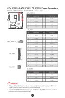
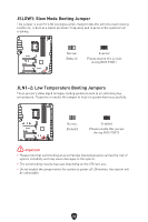
CPU_PWR1~2, ATX_PWR1, PD_PWR1: Power Connectors These connectors allow you to connect an ATX power supply. CPU_PWR1~2 Pin Signal Name Pin Signal Name 1 Ground 2 Ground 3 Ground 4 Ground 5 +12V 6 +12V 7 +12V 8 +12V ATX_PWR1 Pin Signal Name Pin Signal Name 1 +3.3V 2 +3.3V 3 Ground 4 +5V CPU_PWR1~2 8 5 5 Ground 6 +5V 4 1 7 Ground 8 PWR OK 9 5VSB 10 +12V 12 24 11 +12V 12 +3.3V ATX_PWR1 13 +3.3V 14 -12V 15 Ground 16 PS-ON# 1 13 17 Ground 18 Ground 19 Ground 20 Res 21 +5V 22 +5V 3 6 PD_PWR1 1 4 23 +5V PD_PWR1 24 Ground Pin Signal Name Pin Signal Name 1 +12v 2 +12v 3 +12v 4 Ground 5 Ground 6 Ground ⚠ Important ∙ Make sure that all the power cables are securely connected to a proper ATX power supply to ensure stable operation of the motherboard. ∙ To achieve USB PD 60W fast charging for JUSB6, the PD_PWR1 connector needs to be connected to the power supply unit. 47
-
 1
1 -
2
-
3
-
4
-
5
-
6
-
7
-
8
-
9
-
10
-
11
-
12
-
13
-
14
-
15
-
16
-
17
-
18
-
19
-
20
-
21
-
22
-
23
-
24
-
25
-
26
-
27
-
28
-
29
-
30
-
31
-
32
-
33
-
34
-
35
-
36
-
37
-
38
-
39
-
40
-
41
-
 42
42 -
 43
43 -
 44
44 -
 45
45 -
 46
46 -
 47
47 -
 48
48 -
 49
49 -
 50
50 -
 51
51 -
 52
52 -
53
-
54
-
55
-
56
-
57
-
58
-
59
-
60
-
61
-
62
-
63
-
64
-
65
-
66
-
67
-
68
-
69
-
70
-
71
-
72
-
73
-
74
-
75
-
76
-
77
-
78
-
79
-
80
-
81
-
82
-
83
-
84
-
85
 |
 |
