MSI MEG Z790 ACE MAX User Manual 1 - Page 20
Buttons, Jumpers, Switches, LED Features, Back Panel, Connectors, I/O Controller
 |
View all MSI MEG Z790 ACE MAX manuals
Add to My Manuals
Save this manual to your list of manuals |
Page 20 highlights
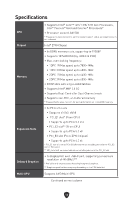
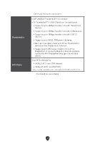
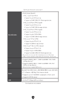
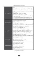
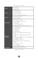
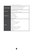
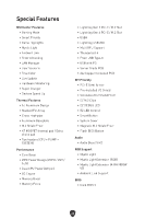
Buttons Jumpers Switches LED Features Back Panel Connectors I/O Controller Continued from previous column ∙ 1x Power button ∙ 1x Reset button ∙ 1x Clear CMOS jumper ∙ 1x OC safe boot jumper ∙ 1x Slow mode jumper ∙ 2x Low temperature booting jumpers ∙ 1x EZ LED Control switch ∙ 1x Multi-BIOS switch ∙ 1x 4-pin RGB LED connector ∙ 3x 3-pin ARGB Gen2 LED connectors ∙ 4x EZ Debug LED ∙ 1x 2-Digit Debug Code LED ∙ 1x Integrated ARGB LED & system fan connector ∙ 1x Clear CMOS button ∙ 1x Flash BIOS button ∙ 1x Smart button ∙ 2x LAN (RJ45) ports ∙ 3x USB 3.2 Gen 2 10Gbps Type-A ports (From Z790 chipset) ∙ 4x USB 3.2 Gen 2 10Gbps Type-A ports (From Hub- GL3590) ∙ 1x USB 3.2 Gen 2 10Gbps Type-C port (From Z790 chipset) with DisplayPort Alt Mode ∙ 2x Thunderbolt 4 USB-C ports ∙ 2x Mini DisplayPort Inputs (for Thunderbolt 4 pass through) ∙ 2x Wi-Fi Antenna connectors ∙ 5x OFC audio jacks ∙ 1x Optical S/PDIF Out connector NUVOTON NCT6687D-R Controller Chip Continued on next column 20
-
 1
1 -
2
-
3
-
4
-
5
-
6
-
7
-
8
-
9
-
10
-
11
-
12
-
13
-
14
-
 15
15 -
 16
16 -
 17
17 -
 18
18 -
 19
19 -
 20
20 -
 21
21 -
 22
22 -
 23
23 -
 24
24 -
 25
25 -
26
-
27
-
28
-
29
-
30
-
31
-
32
-
33
-
34
-
35
-
36
-
37
-
38
-
39
-
40
-
41
-
42
-
43
-
44
-
45
-
46
-
47
-
48
-
49
-
50
-
51
-
52
-
53
-
54
-
55
-
56
-
57
-
58
-
59
-
60
-
61
-
62
-
63
-
64
-
65
-
66
-
67
-
68
-
69
-
70
-
71
-
72
-
73
-
74
-
75
-
76
-
77
-
78
-
79
-
80
-
81
-
82
-
83
-
84
-
85
 |
 |
