MSI MPG Z790 CARBON MAX WIFI User Manual 1 - Page 2

Contents

Page 2 highlights

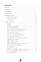
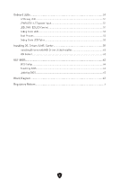
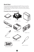
Contents Quick Start...4 Specifications...16 Special Features...21 Package Contents...22 Back Panel Connectors 23 LAN Port LED Status Table 25 Audio Jacks Connection 25 Installing Antennas 27 Overview of Components 28 CPU Socket...29 DIMM Slots...30 PCI_E1~3: PCIe Expansion Slots 31 M2_1~5: M.2 Slots (Key M 32 SATA5~8 & SATA_A1~A2: SATA 6Gb/s Connectors 39 JTBT_U4_1: USB4 Expansion Card Connector 39 JAUD1: Front Audio Connector 40 JFP1, JFP2: Front Panel Connectors 40 CPU_PWR1~2, ATX_PWR1: Power Connectors 41 JCI1: Chassis Intrusion Connector 42 JUSB4: USB 3.2 Gen 2x2 Type-C front panel Connector 43 JUSB3: USB 3.2 Gen 1 Connector 43 JUSB1~2: USB 2.0 Connectors 44 JTPM1: TPM Module Connector 44 CPU_FAN1, PUMP_FAN1, SYS_FAN1~5: Fan Connectors 45 JBAT1: Clear CMOS (Reset BIOS) Jumper 46 BAT1:CMOS Battery 46 JRGB1: RGB LED connector 47 JARGB_V2_1~3: A-RAINBOW V2 (ARGB Gen2) LED connectors 48 JAF_1: Integrated ARGB LED & System Fans Connector 49 JOCFS1: Safe Boot Jumper 50 2

  • 1
  • 2
  • 3
  • 4
  • 5
  • 6
  • 7
  • 8
  • 9
  • 10
  • 11
  • 12
  • 13
  • 14
  • 15
  • 16
  • 17
  • 18
  • 19
  • 20
  • 21
  • 22
  • 23
  • 24
  • 25
  • 26
  • 27
  • 28
  • 29
  • 30
  • 31
  • 32
  • 33
  • 34
  • 35
  • 36
  • 37
  • 38
  • 39
  • 40
  • 41
  • 42
  • 43
  • 44
  • 45
  • 46
  • 47
  • 48
  • 49
  • 50
  • 51
  • 52
  • 53
  • 54
  • 55
  • 56
  • 57
  • 58
  • 59
  • 60
  • 61
  • 62
  • 63
  • 64
  • 65
  • 66
  • 67
  • 68
  • 69
  • 70
  • 71
  • 72
  • 73
  • 74
  • 75
  • 76
  • 77
  • 78

2
Contents
Quick Start
.....................................................................................................................
4
Specifications
..............................................................................................................
16
Special Features
.........................................................................................................
21
Package Contents
......................................................................................................
22
Back Panel Connectors
.............................................................................................
23
LAN Port LED Status Table
..................................................................................
25
Audio Jacks Connection
.......................................................................................
25
Installing Antennas
...............................................................................................
27
Overview of Components
...........................................................................................
28
CPU Socket
...........................................................................................................
29
DIMM Slots
............................................................................................................
30
PCI_E1~3: PCIe Expansion Slots
..........................................................................
31
M2_1~5: M.2 Slots (Key M)
...................................................................................
32
SATA5~8 & SATA_A1~A2: SATA 6Gb/s Connectors
.............................................
39
JTBT_U4_1: USB4 Expansion Card Connector
....................................................
39
JAUD1: Front Audio Connector
............................................................................
40
JFP1, JFP2: Front Panel Connectors
...................................................................
40
CPU_PWR1~2, ATX_PWR1: Power Connectors
...................................................
41
JCI1: Chassis Intrusion Connector
.......................................................................
42
JUSB4: USB 3.2 Gen 2x2 Type-C front panel Connector
.....................................
43
JUSB3: USB 3.2 Gen 1 Connector
........................................................................
43
JUSB1~2: USB 2.0 Connectors
.............................................................................
44
JTPM1: TPM Module Connector
...........................................................................
44
CPU_FAN1, PUMP_FAN1, SYS_FAN1~5: Fan Connectors
..................................
45
JBAT1: Clear CMOS (Reset BIOS) Jumper
...........................................................
46
BAT1:
CMOS Battery
............................................................................................
46
JRGB1: RGB LED connector
.................................................................................
47
JARGB_V2_1~3: A-RAINBOW V2 (ARGB Gen2) LED connectors
.........................
48
JAF_1:
Integrated ARGB LED & System Fans Connector
..................................
49
JOCFS1: Safe Boot Jumper
..................................................................................
50