MSI MPG Z790 CARBON MAX WIFI User Manual 1 - Page 44
JUSB1~2: USB 2.0 Connectors, JTPM1: TPM Module Connector
 |
View all MSI MPG Z790 CARBON MAX WIFI manuals
Add to My Manuals
Save this manual to your list of manuals |
Page 44 highlights
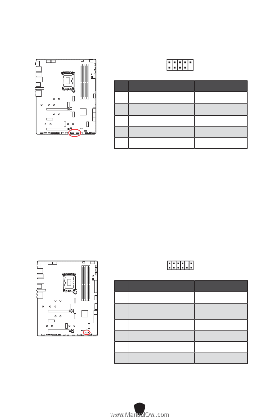
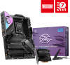
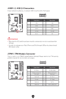
JUSB1~2: USB 2.0 Connectors These connectors allow you to connect USB 2.0 ports on the front panel. 2 10 1 9 Pin Signal Name Pin Signal Name 1 VCC 2 VCC 3 USB0- 4 USB1- 5 USB0+ 6 USB1+ 7 Ground 8 Ground 9 No Pin 10 NC ⚠ Important ∙ Note that the VCC and Ground pins must be connected correctly to avoid possible damage. ∙ In order to recharge your iPad, iPhone and iPod through USB ports, please install MSI Center utility. JTPM1: TPM Module Connector This connector is for TPM (Trusted Platform Module). Please refer to the TPM security platform manual for more details and usages. 2 12 1 11 Pin Signal Name Pin Signal Name 1 SPI Power 2 SPI Chip Select 3 Master In Slave Out (SPI Data) 4 Master Out Slave In (SPI Data) 5 Reserved 6 SPI Clock 7 Ground 8 SPI Reset 9 Reserved 10 No Pin 11 Reserved 12 Interrupt Request 44
-
 1
1 -
2
-
3
-
4
-
5
-
6
-
7
-
8
-
9
-
10
-
11
-
12
-
13
-
14
-
15
-
16
-
17
-
18
-
19
-
20
-
21
-
22
-
23
-
24
-
25
-
26
-
27
-
28
-
29
-
30
-
31
-
32
-
33
-
34
-
35
-
36
-
37
-
38
-
 39
39 -
 40
40 -
 41
41 -
 42
42 -
 43
43 -
 44
44 -
 45
45 -
 46
46 -
 47
47 -
 48
48 -
 49
49 -
50
-
51
-
52
-
53
-
54
-
55
-
56
-
57
-
58
-
59
-
60
-
61
-
62
-
63
-
64
-
65
-
66
-
67
-
68
-
69
-
70
-
71
-
72
-
73
-
74
-
75
-
76
-
77
-
78
 |
 |