Mackie CFX12.mkII Owner's Manual - Page 11
Tape Input, Tape Output, Phones, Efx Foot Switch, Ac Power Input, Power Switch, Power Status - mono mode
 |
View all Mackie CFX12.mkII manuals
Add to My Manuals
Save this manual to your list of manuals |
Page 11 highlights
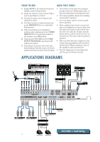
TAPE INPUT Patch the outputs of your intermission entertainment here. Any line-level mono or stereo device can be used: tape, CD player, television audio, etc. See BREAK SWITCH for more information. When connecting a mono device (just one cord), you'll need a "Y-splitter" RCA adapter. It turns a mono output cord into two cords; so both the left and right tape input jacks can be patched. This adapter is widely available. TAPE OUTPUT Use these jacks to capture the entire performance to tape. The signal at these jacks is the main mix, after the MAIN INSERT but before the MAIN MIX Fader . The main mix signal will be present at these jacks regardless of the position of the MAIN MIX Fader. PHONES The stereo signal at these jacks is the same as at the MAIN OUT , but with two important differences: After the MAIN MIX Fader , the mix is sent through the PHONES LEVEL control, allowing you to set levels as desired, without disturbing the main mix level. When a channel's SOLO PFL is engaged, the main mix signal at this output will be replaced by the solo signal, allowing the engineer to audition channels without disturbing the main mix. The stereo PHONES jack will drive any standard headphones to very loud levels. Walkperson-type phones can also be used with an appropriate adapter. Note: Please see the "Safety Instructions" on page 2 for information on hearing protection. EFX FOOT SWITCH You can connect a normally-open foot switch to this connector to duplicate the function of the BYPASS switch, located in the EMAC EFFECTS PROCESSOR . Closing the switch connection causes the EFX BYPASS indicator to light and mutes the effects. Note: When a foot switch is plugged into the FOOT SWITCH jack, the BYPASS switch is disabled. Just like the BYPASS switch, this affects only the internal EMAC EFFECTS PROCESSOR and not any device plugged into STEREO EFX RETURN 2 . LAMP This BNC-type connector will accept almost any of the widely available 12VDC 0.5 amp gooseneck lamps, made by Littlite® and others. If your work involves mixing in the back of dark theaters, this lamp will likely become your best friend. SLEEVE TIP SLEEVE TIP RING (RIGHT) TIP (LEFT) SLEEVE (SHIELD) TRS HEADPHONE WIRING TIP (HOT) SLEEVE (GROUND) TS FOOTSWITCH WIRING AC POWER INPUT This IEC Socket is where you connect the supplied AC linecord to provide AC power to the CFX mixer. Plug the cord into a suitable AC outlet, properly grounded and capable of delivering adequate current. If you happen to lose the AC linecord, replacements are available at any office/computer supply store. POWER SWITCH POWER STATUS The POWER switch is located on the rear panel, adjacent to the AC Power Input . Push the right side of the switch labeled "ON" to turn the mixer on; you should see the POWER STATUS LED glow in confirmation. Press the left side of this switch to put the mixer into standby mode. It will not function, but the circuits are still live. To remove AC power, either turn off the AC mains supply, or unplug the power cord from the mixer and the AC mains supply. POWER ON CFX12 12 CHANNEL COMPACT INTEGRAT MONO PLUG INSERT ALL THE WAY IN TO THE "SECOND CLICK" TIP O RING DIRECT OUT WITH SIGNAL INTERRUPTION TO MASTER FOR US (TIP = OPTIONAL USES FOR 48v POWER STATUS LEFT RIGHT CLIP 22 10 7 4 11
-
 1
1 -
2
-
3
-
4
-
5
-
 6
6 -
 7
7 -
 8
8 -
 9
9 -
 10
10 -
 11
11 -
 12
12 -
 13
13 -
 14
14 -
 15
15 -
 16
16 -
17
-
18
-
19
-
20
-
21
-
22
-
23
-
24
 |
 |
