Magnavox 37MF301B Owners Manual - Page 9
Control Panel, Terminals, Side Panel, Rear Panel - remote
 |
View all Magnavox 37MF301B manuals
Add to My Manuals
Save this manual to your list of manuals |
Page 9 highlights
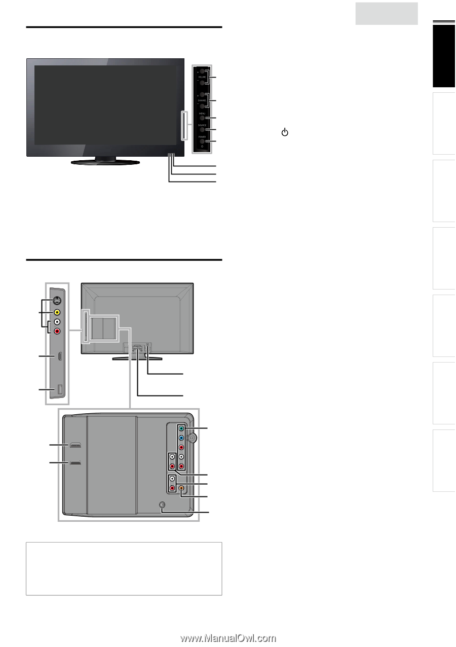
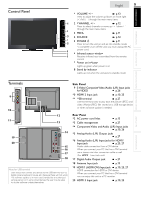
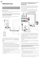
INTRODUCTION PREPARATION Control Panel English 9 1 VOLUME + / − ➠ p.13 Press to adjust the volume up /down or move right (+) / left (−) through the main menu items. 1 2 CHANNEL + / − ➠ p.12 Press to select channels or move up (+) / down (−) through the main menu items. 2 3 MENU ➠ p.15 3 4 SOURCE ➠ p.12 4 5 POWER ➠ p.11 5 Press to turn the unit on and go into standby mode. To completely turn off the unit, you must unplug the AC 6 power cord. 7 6 Infrared sensor window 8 Receives infrared rays transmitted from the remote control. 7 Power on indicator Lights up green when power is on. 8 Stand by indicator Lights up red when the unit goes to standby mode. WATCHING TV USING FUNCTIONS CONNECTING DEVICES USEFUL TIPS Terminals 9 10 11 19 20 12 13 14 15 16 17 18 Note for USB terminal • User should not connect any devices to the USB terminal such as digital camera, keyboard, mouse, etc. (because these will not work). • The software update is, in most cases, handled by an authorized service person or in some circumstances the user may be asked to do the software update themselves. Side Panel 9 S-Video/Composite Video/Audio (L/R) Input jacks for VIDEO ➠ p.26 10 HDMI 2 Input jack ➠ p.10, 25 11 USB terminal ➠ p.27 Use this terminal only to play back the picture (JPEG) and video (Motion JPEG) files stored on a USB storage device, or when software update is needed. Rear Panel 12 AC power cord Inlet ➠ p.10 13 Cable management ➠ p.27 14 Component Video and Audio (L/R) Input jacks ➠ p.10, 26 15 Analog Audio (L/R) Output jacks ➠ p.27 16 Analog Audio (L/R) Input jacks for HDMI 1 Input jack ➠ p.25, 27 Audio cable connection from a DVI device. When you connect your PC that has a DVI terminal, use a stereo mini plug conversion cable as well. (For HDMI 1 Input jack only) 17 Digital Audio Output jack ➠ p.27 18 Antenna Input jack ➠ p.10 19 HDMI 1 (HDMI-DVI) Input jack ➠ p.10, 25, 27 HDMI connection for HDMI or DVI device. When you connect your PC that has a DVI terminal, you can enjoy this unit as a PC monitor. 20 HDMI 3 Input jack ➠ p.10, 25 INFORMATION
-
 1
1 -
2
-
3
-
 4
4 -
 5
5 -
 6
6 -
 7
7 -
 8
8 -
 9
9 -
 10
10 -
 11
11 -
 12
12 -
 13
13 -
 14
14 -
15
-
16
-
17
-
18
-
19
-
20
-
21
-
22
-
23
-
24
-
25
-
26
-
27
-
28
-
29
-
30
-
31
-
32
-
33
 |
 |