Magnavox W-10CR Window AC Owners Manual - Page 11
Installation Instructions
 |
View all Magnavox W-10CR manuals
Add to My Manuals
Save this manual to your list of manuals |
Page 11 highlights
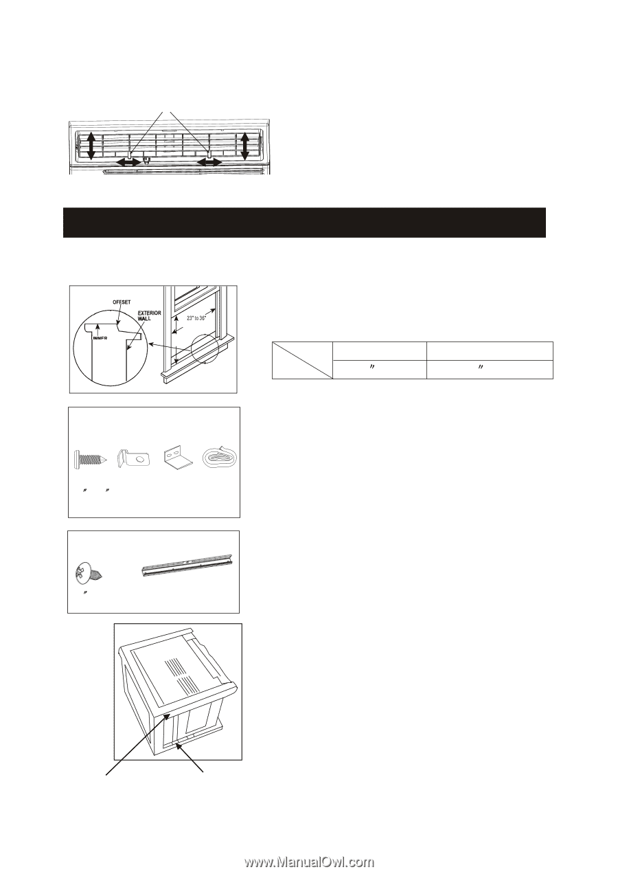
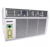
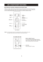
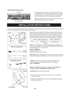
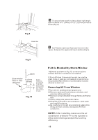
Air Directional Louvers Levers Air Direction The louvers will allow you to direct the air flow UP or DDOOWWNN(o(onnlysoonmseommoedmelosd) ealnsd) aLnedft Loer fRt iogrhRt ight throughout the room as needed. Pivot horizontal louvers until they are in the preferred direction. Move the Levers from side to side until the desired LEFT/RIGHT direction iiss oobbttaaiinneedd.. INSTALLATION INSTRUCTIONS Your air conditioner is designed to be installed in standard double hung windows with opening widths of 23 to 36 inches(58.4cm to 91.4cm) (See Fig.D). Fig. D WINDOW SILL INTERIOR WALL 58.4cm to 91.4cm 15.5''min (39.4cm) Wooden Windows Mounting Hardware Lower sash must open sufficiently to allow a clear vertical opening of following size (see Table 1).Side louvers and the rear of the AC must have clear air space to allow enough airflow through the condenser,for heat removal. The rear of the unit must be outdoors, not inside a building or garage. Model 5000~8000Btu/h Size 14 (35.6cm) 10000~12000Btu/h 15-1/2 (39.4cm) Table 1 NOTE: Save Carton and these Installation Instructions for future reference. The carton is the best way to store unit during winter or when not in use. TOOLS NEEDED: Phillips Screw Driver Drill(If pilot holes are needed) 3/4 (or 1/2 ) Lock Frame Sash Lock Window sash Screws (2) (1) seal foam (7) (1) CAUTION: When handling unit, be careful to avoid cuts from sharp metal edges and aluminum fins on front and rear coils. Top Rail Hardware 3/8 Screws (4) Top Rail (1) Fig.E NOTE: The top rail hardware and the following Fig.E, Fig.F and Fig.G are not applicable to units more than 10000Btu/h. Before installing unit, the top rail must be attached on the unit (For
-
 1
1 -
2
-
3
-
4
-
5
-
 6
6 -
 7
7 -
 8
8 -
 9
9 -
 10
10 -
 11
11 -
 12
12 -
 13
13 -
 14
14 -
 15
15 -
 16
16 -
17
-
18
-
19
 |
 |