Makita HR2641X1 HR2631F Instruction Manual - Page 8
Bit angle, when chipping, scaling or demolishing, Depth gauge
 |
View all Makita HR2641X1 manuals
Add to My Manuals
Save this manual to your list of manuals |
Page 8 highlights
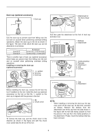
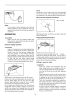
Insert the bit into the tool. Turn the bit and push it in until it engages. After installing, always make sure that the bit is securely held in place by trying to pull it out. 1. Bit 1 2. Chuck cover 2 015255 To remove the bit, pull the chuck cover down all the way and pull the bit out. Bit angle (when chipping, scaling or demolishing) 1. Action mode changing knob 1 015345 The bit can be secured at the desired angle. To change the bit angle, rotate the action mode changing knob to the O symbol. Turn the bit to the desired angle. 3 2 1. Grip base 2. Lock button 3. Depth gauge 1 015347 Press the lock button on the grip base in the direction of arrow shown in the figure and with the lock button being pressed insert the depth gauge into the hex. hole in the grip base. 1. Toothed side of hex hole 1 marking on the grip base 2. Toothed side of the depth gauge 2 015348 At this time, the depth gauge needs to be inserted so that its toothed side is directed to the toothed side of hex hole marking on the grip base as shown in the figure. 1 1. Lock button 015346 Rotate the action mode changing knob to the symbol. Then make sure that the bit is securely held in place by turning it slightly. Depth gauge The depth gauge is convenient for drilling holes of uniform depth. 015349 Adjust the depth gauge to the desired depth by moving it back and forth while pressing the lock button. After the adjustment, release the lock button to lock the depth gauge. 1. Toothed side of 2 1 hex hole marking on the grip base 2. Toothed side of the depth gauge 015350 NOTE: • Inserting the depth gauge with its toothed side not directed to the toothed side of hex hole marking on the grip base as shown in the figure does not allow the depth gauge to be locked. 8
-
 1
1 -
2
-
 3
3 -
 4
4 -
 5
5 -
 6
6 -
 7
7 -
 8
8 -
 9
9 -
 10
10 -
 11
11 -
 12
12 -
 13
13 -
14
-
15
-
16
-
17
-
18
-
19
-
20
-
21
-
22
-
23
-
24
-
25
-
26
-
27
-
28
-
29
-
30
-
31
-
32
-
33
-
34
-
35
-
36
-
37
-
38
-
39
-
40
 |
 |
