Makita LS1040 Owners Manual - Page 14
Vertical vise, Horizontal vise optional accessory - parts
 |
View all Makita LS1040 manuals
Add to My Manuals
Save this manual to your list of manuals |
Page 14 highlights
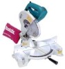
CAUTION: 001767 • When performing left bevel cuts, flip the fence over to the left position as shown in the figure. Otherwise, it will contact the blade or a part of the tool, causing possible 1 serious injury to the operator. 1. Sub-fence 1 2 3 4 5 1. Vise arm 2. Vise rod 3. Guide fence 4. Holder 5. Holder assembly 6. Vise knob 7. Screw 001796 6 7 Vertical vise The vertical vise can be installed in two positions on either the left or right side of the guide fence or the holder assembly (optional accessory). Insert the vise rod into the hole in the guide fence or the holder assembly and tighten the screw to secure the vise rod. Position the vise arm according to the thickness and shape of the workpiece and secure the vise arm by tightening the screw. If the screw to secure the vise arm contacts the guide fence, install the screw on the opposite side of vise arm. Make sure that no part of the tool contacts the vise when lowering the handle all the way. If some part contacts the vise, re-position the vise. Press the workpiece flat against the guide fence and the turn base. Position the workpiece at the desired cutting position and secure it firmly by tightening the vise knob. CAUTION: • The workpiece must be secured firmly against the turn base and guide fence with the vise during all operations. 3 4 1. Vise knob 2. Projection 3. Vise shaft 4. Base 14 001807 Horizontal vise (optional accessory) 21 The horizontal vise can be installed on either the left or right side of the base. When performing 15° or greater miter cuts, install the horizontal vise on the side opposite the direction in which the turn base is to be turned. By turning the vise knob counterclockwise, the screw is released and the vise shaft can be moved rapidly in and out. By turning the vise knob clockwise, the screw remains secured. To grip the workpiece, turn the vise knob gently clockwise until the projection reaches its topmost position, then fasten securely. If the vise knob is forced in or pulled out while being turned clockwise,
-
 1
1 -
2
-
3
-
4
-
5
-
6
-
7
-
8
-
 9
9 -
 10
10 -
 11
11 -
 12
12 -
 13
13 -
 14
14 -
 15
15 -
 16
16 -
 17
17 -
 18
18 -
 19
19 -
20
-
21
-
22
-
23
-
24
-
25
-
26
-
27
-
28
-
29
-
30
-
31
-
32
 |
 |
