Makita LS1040 Owners Manual - Page 15
Operation
 |
View all Makita LS1040 manuals
Add to My Manuals
Save this manual to your list of manuals |
Page 15 highlights
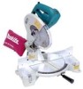
the projection may stop at an angle. In this case, turn the vise knob back counterclockwise until the screw is released, before turning again gently clockwise. The maximum width of the workpiece which can be secured by the horizontal vise is 130 mm (5 - 1/8"). CAUTION: • Grip the workpiece only when the projection is at the topmost position. Failure to do so may result in insufficient securing of the workpiece. This could cause the workpiece to be thrown, cause damage to the blade or cause the loss of control, which can result in PERSONAL INJURY. 1 2 1. Holder 2. Holder assembly 2 1. Holder assembly 2. Rod 12 002247 Holders and holder assembly (optional accessories) The holders and the holder assembly can be installed on either side as a convenient means of supporting workpieces horizontally. Install them as shown in the figure. Then tighten the screws firmly to secure the holders and the holder assembly. 002246 When cutting long workpieces, use the holder-rod assembly (optional accessory). It consists of two holder assemblies and two rods 12. CAUTION: • Always support long workpieces level with the top surface of the turn base for accurate cuts and to prevent 1 dangerous loss of control of the tool. OPERATION CAUTION: • Before use, be sure to release the handle from the lowered position by pulling the stopper pin. • Make sure the blade is not contacting the workpiece, etc. before the switch is turned on. 15
-
 1
1 -
2
-
3
-
4
-
5
-
6
-
7
-
8
-
9
-
 10
10 -
 11
11 -
 12
12 -
 13
13 -
 14
14 -
 15
15 -
 16
16 -
 17
17 -
 18
18 -
 19
19 -
 20
20 -
21
-
22
-
23
-
24
-
25
-
26
-
27
-
28
-
29
-
30
-
31
-
32
 |
 |
