Makita LS1040 Owners Manual - Page 9
Kerf board, Maintaining maximum cutting capacity, Adjusting the miter angle - miter saw
 |
View all Makita LS1040 manuals
Add to My Manuals
Save this manual to your list of manuals |
Page 9 highlights
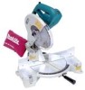
1 1. Kerf board 2. Turn base 002256 2 Kerf board This tool is provided with the kerf board in the turn base to minimize tearing on the exit side of a cut. If the kerf groove has not yet been cut in the kerf board by the factory, you should cut the groove before actually using the tool to cut a workpiece. Switch on the tool and lower the blade gently to cut a groove in the kerf board. 2 1 1. Socket wrench 2. Adjusting bolt 2 1 002257 Maintaining maximum cutting capacity This tool is factory adjusted to provide the maximum cutting capacity for a 255 mm (10") saw blade. When installing a new blade, always check the lower limit position of the blade and if necessary, adjust it as follows: First, unplug the tool. Lower the handle completely. Use the socket wrench to turn the adjusting bolt until the periphery of the blade extends slightly below the top surface of the turn base at the point where the front face of the guide fence 001540 meets the top surface of the turn base. With the tool unplugged, rotate the blade by hand while holding the handle all the way down to be sure that the blade does not contact any part of the lower base. Re-adjust slightly, if necessary. 3 1. Top surface ot turn base 2. Periphery of blade 3. Guide fence CAUTION: • After installing a new blade, always be sure that the blade does not contact any part of the lower base when the handle is lowered completely. Always do this with the tool unplugged. 4 3 1. Pointer 2. Lock lever 3. Grip 4. Miter scale 001778 1 2 Adjusting the miter angle Loosen the grip by turning counterclockwise. Turn the turn base while pressing down the lock lever. When you have moved the grip to the position where the pointer points to the desired angle on the miter scale, securely tighten the grip clockwise. CAUTION: • When turning the turn base, be sure to raise the handle fully. 9
-
 1
1 -
2
-
3
-
 4
4 -
 5
5 -
 6
6 -
 7
7 -
 8
8 -
 9
9 -
 10
10 -
 11
11 -
 12
12 -
 13
13 -
 14
14 -
15
-
16
-
17
-
18
-
19
-
20
-
21
-
22
-
23
-
24
-
25
-
26
-
27
-
28
-
29
-
30
-
31
-
32
 |
 |
