Makita MAC5501G Instruction Manual - Page 10
Description Of, Operation Con't, Installation And, Break-in Procedures - air filter
 |
View all Makita MAC5501G manuals
Add to My Manuals
Save this manual to your list of manuals |
Page 10 highlights
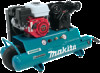
DESCRIPTION OF OPERATION (con't) AIR INTAKE FILTER: This filter is designed to clean air coming into the compressor pump. This filter must always be clean and free from obstructions. See "Maintenance". OUTLET PRESSURE GAUGE: The outlet pressure gauge indicates the air pressure available at the outlet side of the regulator. This pressure is controlled by the regulator and is always less or equal to the tank pressure. See "Operating Procedures". AIR COMPRESSOR PUMP: To compress air, the pistons move up and down in the cylinder. On the down stroke, air is drawn in through the air intake valve. The exhaust valve remains closed. On the upstroke of the piston, air is compressed. The intake valve closes and compressed air is forced out through the exhaust valve, through the outlet tube, through the check valve and into the air tank. Useable air is not available until the compressor has raised the air tank pressure above that required at the air outlet. UNLOADER VALVE: When the compressor pumps the factory set amount of air into the tank, the unloader will blow off. This puts the engine in idle mode and the unloader will open, allowing the unused air to escape preventing over pressuring of the tank. SAFETY VALVE: If the engine does not idle down at its "cut-out" pressure setting, the safety valve will protect against high pressure by "popping out" at its factory set pressure (slightly higher than the unloader valve "cut-out" setting). Do not tamper with or attempt to eliminate the safety relief valve. TANK PRESSURE GAUGE: The tank pressure gauge indicates the air pressure in the tank. REGULATOR: The air pressure coming from the air tank is controlled by the regulator knob. Turn the knob clockwise to increase pressure and counter-clockwise to decrease pressure. To avoid minor re-adjustment after making a change in pressure setting, always approach the desired pressure from a lower pressure. When reducing from a higher to a lower setting, first reduce to some pressure less than desired pressure. Depending on the air requirements of each particular accessory, the outlet regulated air pressure may have to be adjusted while you are operating the accessory. INSTALLATION AND BREAK-IN PROCEDURES LOCATION OF THE AIR COMPRESSOR Locate the air compressor in a clean, dry, and well-ventilated area. The air filter must be kept clear of obstructions, which could reduce air delivery of the air compressor. The air compressor should be located at least 12 inches away from the wall or other obstructions that will interfere with the flow of air. The air compressor head and shroud are designed to allow for proper cooling. If humidity is high, an air filter can be installed on the air outlet adapter to remove excessive moisture. Follow the instructions packaged with the air filter for proper installation. Page 10
-
 1
1 -
2
-
3
-
4
-
 5
5 -
 6
6 -
 7
7 -
 8
8 -
 9
9 -
 10
10 -
 11
11 -
 12
12 -
 13
13 -
 14
14 -
 15
15 -
16
-
17
-
18
-
19
-
20
 |
 |