Marantz SR5004 SR6004 / SR5004 User Manual - English - Page 15
Connecting Video Components
 |
View all Marantz SR5004 manuals
Add to My Manuals
Save this manual to your list of manuals |
Page 15 highlights
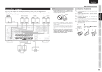
CONNECTIONS FUNCTIONS NAMES AND BASIC ENGLISH CONNECTING VIDEO COMPONENTS DVD player Satellite tuner DIGITAL OUT AUDIO OUT LR VIDEO OUT COMPONENT VIDEO OUT Y CB / PB CR / PR LR AUDIO OUT LR VIDEO OUT LR RL LR LR Video Analog Audio Digital Audio (coaxial) Digital Audio (optical) S-Video IN 1 IN 4 DVD VCR DSS TV IN IN OUT IN IN ANALOG AUDIO COMPONENT VIDEO Y OUT VIDEO IN 3(VCR) OUT(VCR) PB/CB L PR/CR IN 2(DVD) IN 4(DSS) MONITOR OUT R VIDEO, S-VIDEO, COMPONENT JACKS VIDEO JACK The video signal for the VIDEO jacks is the conventional composite video signal. COMPONENT JACK Make component video connections to a TV or monitor with component inputs to produce higher quality video images. Use a component video cable or 3 video cords to connect the component video out jacks on the unit to the monitor. S-VIDEO JACK The video signal is separated into luminance (Y) and color (C) signals for the S-VIDEO jack. BASIC CONNECTIONS Notes • Be sure to connect the left and right audio channels properly. Red connectors are for the R (right) channel, and white connectors are for the L (left) channel. • Be sure to connect the inputs and outputs of the video signals properly. • You may need to setup the digital audio output format of your DVD player, or other digital source components. Refer to the instructions of the each component connected to the digital input jacks. • The unit has a video conversion function. For details on the input and output of the video signals, refer to page 44. • The AUX VIDEO terminal and S-VIDEO terminal cannot be used at the same time. When using the S-VIDEO terminal, do not connect any component to the VIDEO terminal. LR BASIC OPERATION ADVANCED CONNECTIONS SETUP ADVANCED OPERATION TROUBLESHOOTING LR LR LR LR L R LR AUDIO AUDIO OUT IN VIDEO OUT IN VCR RL LR LR DIGITAL OUT AUDIO OUT VIDEO IN TV Y CB / PB CR / PR COMPONENT VIDEO IN Projector LR DIGITAL S-VIDEO VIDEO OUT OUT OUT LR AUDIO OUT Camcorder, portable DVD, Game etc. 13 OTHERS
-
 1
1 -
2
-
3
-
4
-
5
-
6
-
7
-
8
-
9
-
 10
10 -
 11
11 -
 12
12 -
 13
13 -
 14
14 -
 15
15 -
 16
16 -
 17
17 -
 18
18 -
 19
19 -
 20
20 -
21
-
22
-
23
-
24
-
25
-
26
-
27
-
28
-
29
-
30
-
31
-
32
-
33
-
34
-
35
-
36
-
37
-
38
-
39
-
40
-
41
-
42
-
43
-
44
-
45
-
46
-
47
-
48
-
49
-
50
-
51
-
52
-
53
-
54
-
55
-
56
-
57
-
58
-
59
-
60
-
61
-
62
-
63
-
64
-
65
-
66
-
67
-
68
-
69
-
70
-
71
-
72
-
73
-
74
-
75
-
76
-
77
-
78
-
79
-
80
-
81
-
82
-
83
-
84
-
85
-
86
-
87
-
88
-
89
-
90
-
91
-
92
-
93
-
94
-
95
-
96
 |
 |
