Marantz SR6001 SR6001 User Manual - Page 48
Temporarily Turning Off, The Sound, Using The Sleep Timer, Video Convert, I/p Convert
 |
View all Marantz SR6001 manuals
Add to My Manuals
Save this manual to your list of manuals |
Page 48 highlights
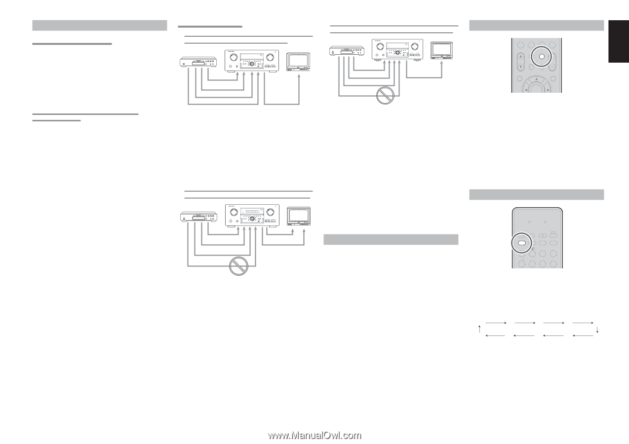
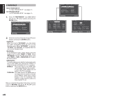
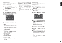
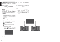
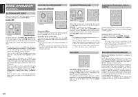
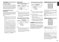
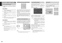
ENGLISH VIDEO CONVERT ANALOG VIDEO CONVERSION The SR6001 is equipped to convert video signals for monitor output. Because of this, indifferent of the connection (VIDEO, S-VIDEO, COMPONENT VIDEO) between the playback device and the SR6001, listening and viewing are possible with a single higher grade cable between the MONITOR OUT terminal of the SR6001 and the monitor. UP-CONVERSION FROM ANALOG VIDEO SIGNALS TO HDMI The up-conversion feature of the SR6001 can output the input analog video signals (for component video signals of 480i, 480p, 1080i and 720p resolution, and S-Video and Video (composite) of 480i resolution) to the HDMI MONITOR terminal. Notes: • HDMI video input is only output to the HDMI MONITOR OUT terminal of the SR6001. If connecting a playback device such as a DVD player to the HDMI input jack, connect the HDMI MONITOR OUT terminal of the SR6001 to a TV monitor. • This mode is unavailable for the REC out terminal. • This mode is unavailable for still picture, fast forward and reverse play on video component. • If, while attempting to use the video convert feature, the SR6001 cannot synchronize with the display device, "NO SIGNAL" appears on the monitor or noise is generated, this feature cannot be used. All of these signs are caused by equipment incompatibility; there is nothing wrong with the SR6001. If this occurs, set "VIDEO CONVERT" in the "VIDEO SETUP" menu to "DISABLE". Next, connect the video input signal to the display component via the MONITOR OUT terminal under VIDEO and the S-video input signal to the display component via the MONITOR OUT terminal under S-VIDEO. • The video convert feature constantly monitors input video signals and determines whether to convert the input signals or not. However, some input video signals cannot be detected correctly. If this occurs, set "VIDEO CONVERT" in the "VIDEO SETUP" menu to "DISABLE". CONNECTION EXAMPLE • When a monitor is connected to the HDMI MONITOR OUT terminal of the SR6001 AV SURROUND RECEIVER SR6001 INPUT SELECTOR PURE DIRECT DSD STANDBY POWER ON/STANDBY PHONES SURROUND MODE AUTO MULTI MULTI SPEAKER BAND T-MODE MEMORY CLEAR PURE DIRECT HT-EQ 7.1CH INPUT MENU ENTER DISPLAY EXIT MultEQ SPEAKERS A/B MIC VOLUME READY DOWN UP DIGITAL AUX 1 INPUT S-VIDEO VIDEO L AUDIO R VIDEO or S-VIDEO or component or HDMI HDMI Notes: • If the resolution of the component video signal input from the playback device is other than 480i, 480p, 1080i or 720p, images are not output from the HDMI MONITOR OUT terminal of the SR6001. • If the resolution of the S-Video or Video signal input from the playback device is other than 480i, images are not output from the HDMI MONITOR OUT terminal of the SR6001. • When a monitor is connected to the VIDEO or SVIDEO MONITOR OUT terminals of the SR6001 AV SURROUND RECEIVER SR6001 INPUT SELECTOR PURE DIRECT DSD DISP MULTI AUTO TUNED SLEEP AUTO SURR DIRECT ST SPKR A B V-OFF PEAK ATT DISC 6.1 MT X 6.1 NIGHT EQ ANALOG DIGITAL AAC PCM SURROUND DIGITAL LCR LFE SL S SR STANDBY POWER ON/STANDBY PHONES SURROUND MODE AUTO MULTI MULTI SPEAKER BAND T-MODE MEMORY CLEAR PURE DIRECT HT-EQ 7.1CH INPUT MENU ENTER DISPLAY EXIT MultEQ SPEAKERS A/B MIC VOLUME READY DOWN UP DIGITAL AUX 1 INPUT S-VIDEO VIDEO L AUDIO R VIDEO or S-VIDEO or component HDMI VIDEO or S-VIDEO Notes: • The HDMI video signal input from the playback device is not output from the VIDEO or S-VIDEO MONITOR OUT terminals of the SR6001. • If the resolution of the component video signal input from the playback device is other than 480i, it is not output from the VIDEO or S-VIDEO MONITOR OUT terminals of the SR6001. • When a monitor is connected to the COMPONENT VIDEO MONITOR OUT terminal of the SR6001 AV SURROUND RECEIVER SR6001 INPUT SELECTOR PURE DIRECT DSD STANDBY POWER ON/STANDBY PHONES SURROUND MODE AUTO MULTI MULTI SPEAKER BAND T-MODE MEMORY CLEAR PURE DIRECT HT-EQ 7.1CH INPUT MENU ENTER DISPLAY EXIT MultEQ SPEAKERS A/B MIC VOLUME READY DOWN UP DIGITAL AUX 1 INPUT S-VIDEO VIDEO L AUDIO R VIDEO or S-VIDEO or component HDMI component Notes: • The HDMI video signal input from the playback device is not output from the COMPONENT VIDEO MONITOR OUT terminal of the SR6001. Notes of OSD menu system: • The setup menu can be displayed through all video out terminals ("HDMI", "COMPONENT", "SVIDEO" and "VIDEO"). • OSD information is output only to the VIDEO and S-VIDEO MONITOR OUT terminals. OSD information is also output when the video conversion feature is on and the video signal input to the VIDEO or S-VIDEO input jack of the SR6001 is converted and output from the COMPONENT VIDEO or HDMI MONITOR OUT terminals. I/P CONVERT The video circuit of the SR6001 is equipped with an I/P conversion feature. When this feature is on, 480i analog video signals (VIDEO, S-VIDEO or COMPONENT VIDEO) input from a playback device can be converted to 480p and progressively output to the COMPONENT VIDEO or HDMI MONITOR OUT terminals of the SR6001. (For setting instructions, see page 39) TEMPORARILY TURNING OFF THE SOUND 7.1CH IN A/D HT-EQ CL 0 +10 MEMO CH/ CAT SPKR A/B MUTE VOLUME MULTI/ CAT M-SPKR INFO MENU ENTER To temporarily silence all speaker outputs such as when interrupted by a phone call, press the MUTE button on the remote. This will interrupt the output to all speakers and the head-phone jack, but it will not affect any recording or dubbing that may be in progress. When the system is muted, the display will show "MUTE" . Press the MUTE button again to return to normal operation. USING THE SLEEP TIMER LEARN SEND SOURCE l/ SET SLEEP DISPLAY OFF ON P.DIRECT SURROUND AUTO 1 CS 4 2 EX/ES 5 LIP SYNC/ dts INPUT 3 BAND VIRTUAL T.MODE 6 To program the SR6001 for automatic standby, press the SLEEP button on the remote. Each press of the button will increase the time before shut down in the following sequence. OFF 10 20 30 40 90 80 70 60 50 The sleep time will be shown for a few seconds in the display on the front panel, and it will count down until the time has elapsed. When the programmed sleep time has elapsed, the unit will automatically turn off. Note that the SLEEP indicator on the display will illuminate when the Sleep function is programmed. To cancel the Sleep function, press the SLEEP button until the display shows "SLEEP OFF" and the SLEEP indicator will disappear. 45
-
 1
1 -
2
-
3
-
4
-
5
-
6
-
7
-
8
-
9
-
10
-
11
-
12
-
13
-
14
-
15
-
16
-
17
-
18
-
19
-
20
-
21
-
22
-
23
-
24
-
25
-
26
-
27
-
28
-
29
-
30
-
31
-
32
-
33
-
34
-
35
-
36
-
37
-
38
-
39
-
40
-
41
-
42
-
 43
43 -
 44
44 -
 45
45 -
 46
46 -
 47
47 -
 48
48 -
 49
49 -
 50
50 -
 51
51 -
 52
52 -
 53
53 -
54
-
55
-
56
-
57
-
58
-
59
-
60
-
61
-
62
-
63
-
64
-
65
-
66
-
67
-
68
-
69
-
70
-
71
 |
 |