Marantz SR7200 User Guide - Page 11
Panel, Connections
 |
View all Marantz SR7200 manuals
Add to My Manuals
Save this manual to your list of manuals |
Page 11 highlights
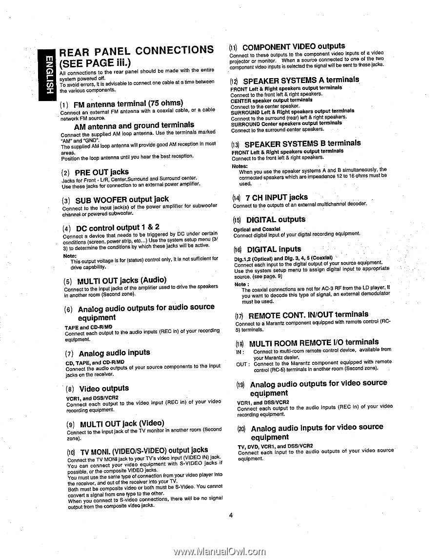
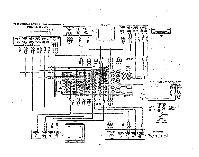
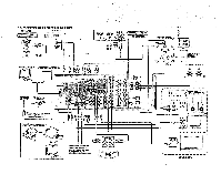
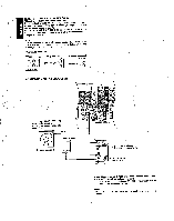
m rC) REAR PANEL CONNECTIONS (SEE PAGE iii.) All connections to the rear panel should be made with the entire system powered off. U) To avoid errors, it is advisable to connect one cable at a time between the various components. (1) FM antenna terminal (75 ohms) Connect an external FM antenna with a coaxial cable, or a cable network FM source. AM antenna and ground terminals Connect the supplied AM loop antenna. Use the terminals marked "AM" and "GND". The supplied AM loop antenna will provide good AM reception in most areas. Position the loop antenna until you hear the best reception. (2) PRE OUT jacks Jacks for Front - UR, Center,Surround and Surround center. Use these jacks for connection to an external power amplifier. (ii) COMPONENT VIDEO outputs Connect to these outputs to the component video inputs of a video projector or monitor. When a source connected to one of the two component video inputs Is selected the signal will be sent to these jacks. (12) SPEAKER SYSTEMS A terminals FRONT Lett & Right speakers output terminals Connect to the front left & right speakers. CENTER speaker output terminals Connect to the center speaker. SURROUND Lett & Right speakers output terminals Connect to the surround (rear) left & right speakers. SURROUND Center speakers output terminals Connect to the surround center speakers. (13) SPEAKER SYSTEMS B terminals FRONT Lett & Right speakers output terminals Connect to the front left & right speakers. Notes: When you use the speaker systems A and B simultaneously, the connected speakers which are impeadance 12 to 16 ohms must be used. (3) SUB WOOFER output jack Connect to the input jack(s) of the power amplifier for subwoofer channel or powered subwoofer. (4) DC control output 1 & 2 Connect a device that needs to be triggered by DC under certain conditions (screen, power strip, etc...) Use the system setup menu (3/ 3) to determine the conditions by which these jacks will be active. Note: This output voltage Is for (status) control only, It is not sufficient for drive capability. (5) MULTI OUT jacks (Audio) Connect to the input jacks of the amplifier used to drive the speakers in another room (Second zone). (6) Analog audio outputs for audio source equipment TAPE and CD-R/MD Connect each output to the audio inputs (REC in) of your recording equipment. (7) Analog audio inputs CD, TAPE, and CD-R/MD Connect the audio outputs of your source components to the input jacks on the receiver. (t 4) 7 CH INPUT jacks Connect to the outputs of an external multichannel decoder. (15) DIGITAL outputs Optical and Coaxial Connect digital input of your digital recording equipment. (16) DIGITAL inputs Dlg.1,2 (Optical) and Dig. 3, 4, 5 (Coaxial) Connect each Input to the digital output of your source equipment. Use the system setup menu to assign digital input to appropriate source. (see page. 9) Note : The coaxial connections are not for AC-3 RE from the LD player, If you want to decode this type of signal, an external demodulator must be used. (17) REMOTE CONT. IN/OUT terminals Connect to a Marantz component equipped with remote control (RC5) terminals. (18) MULTI ROOM REMOTE I/O terminals IN : Connect to multi-room remote control device, available from your Marantz dealer. OUT : Connect to the Marantz component equipped with remote control (RC-5) terminals in another room (Second zone). (8) Video outputs VCR1, and DSSIVCR2 Connect each output to the video input (REC in) of your video recording equipment. (9) MULTI OUT jack (Video) Connect to the input jack of the TV monitor in another room (Second zone). (10) TV MONI. (VIDEO/S-VIDEO) output jacks Connect the TV MONI jack to your TV's video input (VIDEO IN) jack. You can connect your video equipment with S-VIDEO jacks if possible, or the composite VIDEO jacks. You must use the same type of connection from your video player Into the receiver, and out of the receiver into your TV. Both must be composite video or both must be S-Video. You cannot convert a signal from one type to the other. When you connect to S-video connections, there will be no signal output from the composite video jacks. (19) Analog audio outputs for video source equipment VCR1, and DSS/VCR2 Connect each output to the audio inputs (REC in) of your video recording equipment. (20) Analog audio inputs for video source equipment TV, DVD, VCR1, and DSS.rVCR2 Connect each Input to the audio outputs of your video source equipment. 4
-
 1
1 -
2
-
3
-
4
-
5
-
 6
6 -
 7
7 -
 8
8 -
 9
9 -
 10
10 -
 11
11 -
 12
12 -
 13
13 -
 14
14 -
 15
15 -
 16
16 -
17
-
18
-
19
-
20
-
21
-
22
-
23
-
24
-
25
-
26
-
27
-
28
-
29
-
30
-
31
-
32
-
33
-
34
-
35
-
36
-
37
-
38
-
39
-
40
 |
 |