Maytag MEC4430AAB Installation Instructions
Maytag MEC4430AAB - 30 Inch Electric Cooktop Manual
 |
View all Maytag MEC4430AAB manuals
Add to My Manuals
Save this manual to your list of manuals |
Maytag MEC4430AAB manual content summary:
- Maytag MEC4430AAB | Installation Instructions - Page 1
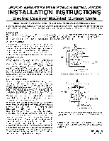
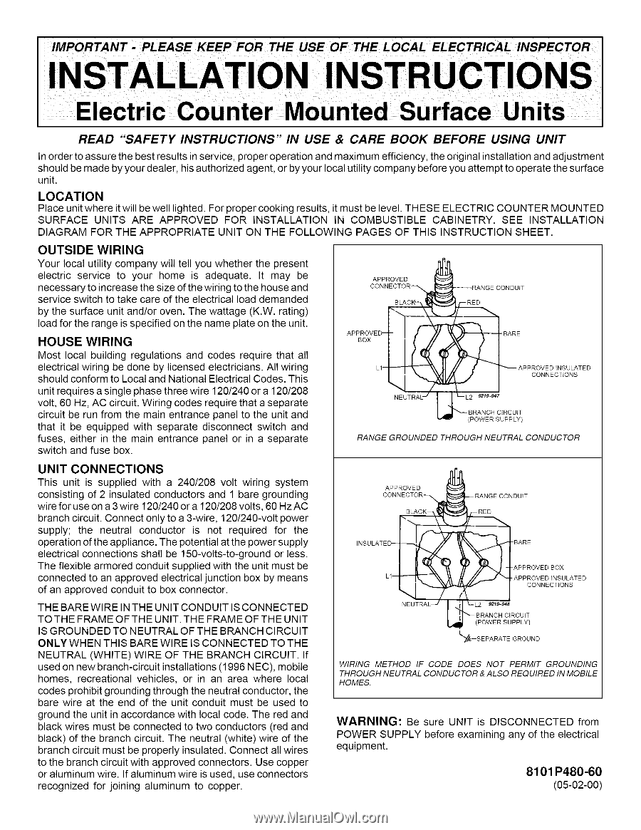
INSTALLATION IN COMBUSTIBLE CABINETRY. SEE INSTALLATION DIAGRAM FOR THE APPROPRIATE UNIT ON THE FOLLOWING PAGES OF THIS INSTRUCTION SHEET. OUTSIDE WIRING Your local utility company will tell you whether the present electric service for the operation of the appliance. The potential at the power - Maytag MEC4430AAB | Installation Instructions - Page 2
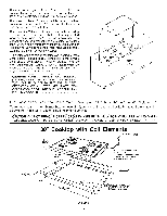
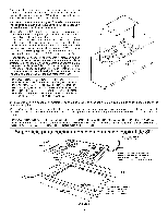
REMOVE GREEN GROUND WIRE FROM MAIN TOP WHEN REPLACING TOP; USECAUT ONTOBE SURE W RESARE NO NCHED UNDER SWTCH SH ELD MAIN 30" Cooktop with Coil Elements LEADS DEPTH FRONT OI UNIT 3/8" FLEXIBLE CABLE3' MIN. FURNISHEDAND INSTALLEDBY MANUFACTURER (CONNECTTO 240/120-VOLT ELECTRICALSERVICE.) C 219 - Maytag MEC4430AAB | Installation Instructions - Page 3
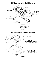
FOR RIGHT ANGLE CONDUIT AND WIRE. FIGURE2 30" Smoothtop Ceramic Cooktop 2 3/4" DEPTH FRONT// OF UNIT 6" WIRE LEADS 3/8" FLEXIBLE CABLE 48" LONG FURNISHED AND INSTALLED BY MANUFACTURER (CONNECT TO 240/120 VOLT ELECTRICAL SERVICE) 29 7/16" 2 I/8" MIN 20 7/16" 4 I/4" CLEARANCE INSIDE - Maytag MEC4430AAB | Installation Instructions - Page 4
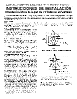
INSTR ON Unidades p mostrador LEA LAS "INSTRUCCIONES DE SEGURIDAD'" EN EL MANUAL DE CUIDADO Y USO ANTES DE USAR LA UNIDAD Para garantizar los mejores resultados en el servicio, el funcionamiento apropiado y la maxima eficiencia, la instalaci6n y el - Maytag MEC4430AAB | Installation Instructions - Page 5
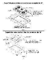
. Quite los cuatro (4) tornillos de montaje de la parte superior principal. (Las lengQetas laterales de las aberturas del PARTE SUPERIOR PRINCIPAL TENGA CUIDADO QUE LOS ALAMBRES NO QUEDEN PELL ZCADOS DEBAJO DEL PROTECTOR DEL NTERRUPTORI Superficie para cocinar con elementos de espiral de 30 - Maytag MEC4430AAB | Installation Instructions - Page 6
M/kS EL ESPAClO LIBRE ADENTRO PARA OBTENER EL/kNGULO CORRECTO DEL CONDUCTOR Y DEL ALAMBRE. FIGURA2 Superficie para cocinar lisa de ceramica de 30" 2 3/4" DE PROFUNDIDAD FRENTE DE LA UNIDAD CONDUCTOR DEL ALAMBRE DE 6" CABLE FLEXIBLE DE 3/8" DE 48" DE LARGO, PROVISTO E INSTALADO POR EL FABRICANTE - Maytag MEC4430AAB | Installation Instructions - Page 7
fonctionnement correct et efficient et des resultats optimums au niveau du service apres-vente, la pose et le reglage initiaux doivent etre realises ) DU CIRCUIT DE D#RIVATION. Dans le cas de circuits de derivation nouvellement installes (NEC 1996), de maisons mobiles, de vehicules de Ioisir ou s'il - Maytag MEC4430AAB | Installation Instructions - Page 8
DE CONSTRUCTION NE SONT PAS CONOUS POUR SUPPORTER LA CHALEUR PRODUITE LORS DU FONCTIONNEMENT D P NCER LES F LS SOUS L I_CRAN PROTECTEUR DES BOUTONS. cuISsoNI FAIRE Plaque de cuisson de 30 pouces avec elements tubulaires FILS CONBUCTEURSBE 0 PO PROFONBEUR BE 3 1/4 PO PBEVANTBE L'APPABEIL I I - Maytag MEC4430AAB | Installation Instructions - Page 9
Plaque de cuisson de 91,4 cm avec elements tubulaires DEVANT DE LA PLAQUE 50,2 CM 8,6 CM DE PROFONDUR C,_,BLE FLEXIBLE DE 13 MM DE DIAM#TRE ET 91,4 CM DE LONG FOURNI ET POSE EN USINE (RACCORDER ,&, UNE ALIMENTATION ELECTRIQUE DE 240/120 V) FIL CONDUCTEUR DE 15,2 CM 6,7 CM MIN. 0,9 CM ARRONDI
-
 1
1 -
 2
2 -
 3
3 -
 4
4 -
 5
5 -
 6
6 -
 7
7 -
8
-
9
 |
 |
READ
"SAFETY
INSTRUCTIONS"
IN USE
& CARE
BOOK
BEFORE
USING
UNIT
In order to assure the best results in service, proper operation and maximum efficiency, the original installation and adjustment
should be made by your dealer, his authorized agent, or by your local utility company before you attempt to operate the surface
unit.
LOCATION
Place unit where it will be well lighted. For proper cooking results, it must be level. THESE ELECTRIC
COUNTER
MOUNTED
SURFACE
UNITS
ARE
APPROVED
FOR
INSTALLATION
IN COMBUSTIBLE
CABINETRY.
SEE
INSTALLATION
DIAGRAM
FOR THE APPROPRIATE
UNIT ON THE FOLLOWING
PAGES
OF THIS
INSTRUCTION
SHEET.
OUTSIDE
WIRING
Your local utility company will tell you whether
the present
electric
service
to
your
home
is
adequate.
It
may
be
necessary to increase the size of the wiring to the house and
service switch to take care of the electrical
load demanded
by the surface unit and/or oven. The wattage
(K.W. rating)
load for the range is specified on the name plate on the unit.
HOUSE
WIRING
Most
local building
regulations
and codes require
that all
electrical
wiring be done by licensed
electricians.
All wiring
should conform to Local and National Electrical Codes. This
unit requires a single phase three wire 120/240 or a 120/208
volt, 60 Hz, AC circuit. Wiring codes require that a separate
circuit be run from the main entrance
panel to the unit and
that
it be equipped
with
separate
disconnect
switch
and
fuses,
either in the main entrance
panel or in a separate
switch and fuse box.
UNIT
CONNECTIONS
This
unit is supplied
with
a 240/208
volt
wiring
system
consisting
of 2 insulated
conductors
and 1 bare grounding
wire for use on a 3 wire 120/240 or a 120/208 volts, 60 Hz AC
branch circuit. Connect only to a 3-wire, 120/240-volt power
supply;
the
neutral
conductor
is
not
required
for
the
operation of the appliance. The potential at the power supply
electrical
connections
shall be 150-volts-to-ground
or less.
The flexible
armored conduit supplied with the unit must be
connected to an approved
electrical junction box by means
of an approved
conduit to box connector.
THE BARE WIRE IN THE UNIT CONDUIT
IS CONNECTED
TO THE FRAME OF THE UNIT. THE FRAME OF THE UNIT
IS GROUNDED
TO NEUTRAL OF THE BRANCH CIRCUIT
ONLY WHEN THIS BARE WIRE IS CONNECTED
TO THE
NEUTRAL
(WHITE)
WIRE OF THE BRANCH
CIRCUIT.
If
used on new branch-circuit
installations
(1996 NEC), mobile
homes,
recreational
vehicles,
or in an area where
local
codes prohibit grounding
through the neutral conductor,
the
bare wire at the end of the unit conduit
must be used to
ground the unit in accordance
with local code. The red and
black wires must be connected to two conductors
(red and
black) of the branch circuit. The neutral (white) wire of the
branch circuit must be properly insulated. Connect all wires
to the branch circuit with approved connectors.
Use copper
or aluminum wire. If aluminum wire is used, use connectors
recognized
for joining
aluminum
to copper.
APPROVED
CONNECTOR_
APPRoOxVE_
NEUTRAL'-'
_RANGE
CONDUIT
_
APPROVED
INSULATED
CONNECTIONS
L2
9219-947
BRANCH
CIRCUIT
(POWER
SUPPLY)
RANGE
GROUNDED
THROUGH
NEUTRAL
CONDUCTOR
APPROVED
CONNECTOR-_
INSULATED--
B_
L1--
NEUTRAL
--/
(
--
RANGE
CONDUIT
)_
-BARE
-APPROVED
B©X
"APPRQVEDtNSULATED
CONNECTIONS
i
I._L2
9219-948
BRANCH
CIRCUIT
L_
POWER
SUPPLY
I"_,--S
EPARATE
GROUND
WIRING
METHOD
IF CODE
DOES
NOT
PERMIT
GROUNDING
THROUGH
NEUTRAL
CONDUCTOR
& ALSO REQUIRED
IN MOBILE
HOMES.
WARNING:
Be sure
UNIT
is DISCONNECTED
from
POWER
SUPPLY
before examining
any of the electrical
equipment.
8101
P480-60
(05-02-00)