Maytag MEC4430AAB Installation Instructions - Page 2
Cooktop, Elements - dimensions
 |
View all Maytag MEC4430AAB manuals
Add to My Manuals
Save this manual to your list of manuals |
Page 2 highlights
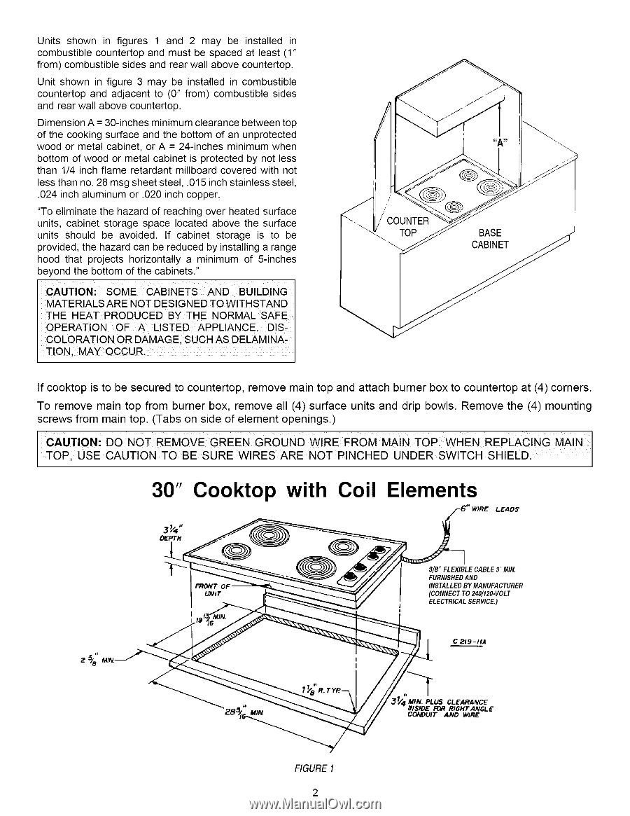
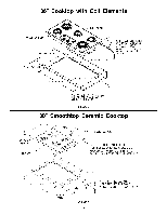
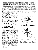
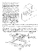
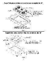
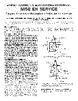
Units shownin figures1 and 2 may be installedin combustiblceountertoapndmustbespacedat least(1" from)combustiblseidesandrearwallabovecountertop. Unitshownin figure3 may be installedin combustible countertopandadjacento (0"from)combustiblesides andrearwallabovecountertop. DimensioAn =30-inchems inimumclearancbeetweentop ofthe cookingsurfaceandthe bottomof anunprotected woodor metalcabineto, r A = 24-inchesminimumwhen bottomofwoodor metalcabineits protectedby notless than1/4inchflameretardanmt illboardcoveredwithnot lessthanno.28msgsheest teel,.015inchstainlessteel, .024inchaluminumor .020inchcopper. "Toeliminatethe hazardofreachingoverheatedsurface units,cabinetstoragespacelocatedabovethe surface units shouldbe avoided.If cabinetstorageis to be providedt,hehazardcanbereducedby installinga range hoodthat projectshorizontallya minimumof 5-inches beyondthe bottomofthecabinets." CAUTION: SOMECABINETSAND BUILDING MATERIALSARENOTDESIGNETDOWITHSTAND THE HEATPRODUCEBDY THE NORMALSAFE OPERATIONOF A LISTEDAPPLIANCE,DISCOLORATIONORDAMAGES,UCHASDELAMINATION,MAYOCCUR, COUNTER TOP BASE If cooktop is to be secured to countertop, remove main top and attach burner box to countertop at (4) corners. To remove main top from burner box, remove all (4) surface units and drip bowls. Remove the (4) mounting screws from main top. (Tabs on side of element openings.) CAUTION:DO NOT REMOVE GREEN GROUND WIRE FROM MAIN TOP WHEN REPLACING TOP; USECAUT ONTOBE SURE W RESARE NO NCHED UNDER SWTCH SH ELD MAIN 30" Cooktop with Coil Elements LEADS DEPTH FRONT OI UNIT 3/8" FLEXIBLE CABLE3' MIN. FURNISHEDAND INSTALLEDBY MANUFACTURER (CONNECTTO 240/120-VOLT ELECTRICALSERVICE.) C 219-1tA FIGURE1 MtN. PLUS CLEARANCE INSIDE FOR RIGHT ANGLE CONDUIT AND WIRE
-
 1
1 -
 2
2 -
 3
3 -
 4
4 -
 5
5 -
 6
6 -
 7
7 -
 8
8 -
9
 |
 |