Maytag MGDZ400TQ Use and Care Guide - Page 15
theshutoff, valve, inthesupply, lille,lhevalve, isopenwhen, thehandle, isparallel, thegaspipe. - gas dryer
 |
UPC - 883049064963
View all Maytag MGDZ400TQ manuals
Add to My Manuals
Save this manual to your list of manuals |
Page 15 highlights
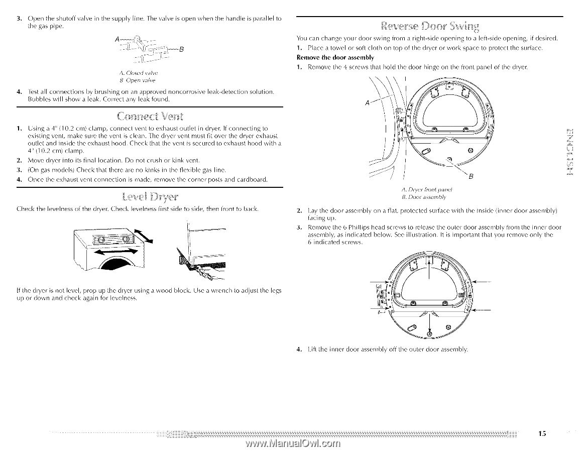
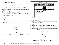
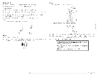
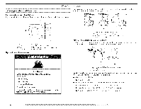
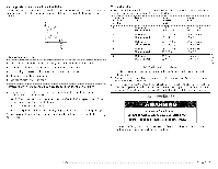
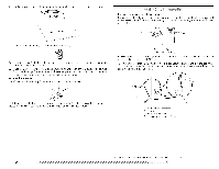
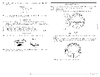
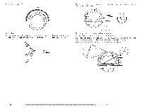
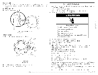
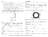
3. Opentheshutovffalveinthesuppllyille,lhevalveisopenwhenthehandliesparalletol thegaspipe. A. Closed valve B. Open valve 4. [_st all connections by brushing on an approved noncorrosive leak-detection solution. Bubbles will show a leak. Correct any leak found. £o nect %n 1. Using a 4" (10.2 cm) clamp, connect vent to exhaust outlet in dryer. If connecting to existing vent, make sure the vent is clean. [-he dryer vent must fit over the dryer exhaust outlet and inside the exhaust hood. Check that the vent is secured to exhaust hood with a 4" (10.2 cm) clamp. 2. Move dryer into its final location. Do not crush or kink vent. 3. (On gas models) Check that there are no kinks in the flexible gas line. 4. Once the exhaust vent connection is made, remove the corner posts and cardboard. Check the levelness of the dryer. Check levelness first side to side, then front to back. You can change your door swing from a right-side opening to a left-side opening, if desired. 1. Place a towel or soft cloth on top of the dryer or work space to protect the surface. Remove the door assembly 1. Remove the 4 screws that hold the door hinge on the front panel of the dryer. \ A. Dryer front panel B. Door assembly 2. I.ay the door assembly on a flat, protected surface with the inside (inner door assembly/ facing up. 3. Remove the 6 Phillips head screws to release the outer door assembly from the inner door assembly, as indicated below. See illustration. It is important that you remove only the 6 indicated screws. If the dryer is not level, prop up the dryer using a wood block. Use a wrench to adjust the legs up or down and check again for levelness. 4. I.ift the inner door assembly off the outer door assembly.
-
 1
1 -
2
-
3
-
4
-
5
-
6
-
7
-
8
-
9
-
 10
10 -
 11
11 -
 12
12 -
 13
13 -
 14
14 -
 15
15 -
 16
16 -
 17
17 -
 18
18 -
 19
19 -
 20
20 -
21
-
22
-
23
-
24
-
25
-
26
-
27
-
28
-
29
-
30
-
31
-
32
-
33
-
34
-
35
-
36
-
37
-
38
-
39
-
40
-
41
-
42
-
43
-
44
-
45
-
46
-
47
-
48
-
49
-
50
-
51
-
52
-
53
-
54
-
55
-
56
-
57
-
58
-
59
-
60
-
61
-
62
-
63
-
64
-
65
-
66
-
67
-
68
-
69
-
70
-
71
-
72
-
73
-
74
-
75
-
76
-
77
-
78
-
79
-
80
-
81
-
82
-
83
-
84
 |
 |