Metabo WEVF 10-125 Quick Inox Operating Instructions - Page 16
Overview, Commissioning, Attaching the grinding wheel - set
 |
View all Metabo WEVF 10-125 Quick Inox manuals
Add to My Manuals
Save this manual to your list of manuals |
Page 16 highlights
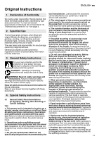
en ENGLISH - Ensure good ventilation of the workplace and keep it clean using a vacuum cleaner. Sweeping or blowing stirs up dust. - Vacuum or wash protective clothing. Do not blow, beat or brush. 5. Overview See page 2. 1 Clip to tighten/release the (tool-free) clamping nut manually * 2 Clamping nut (tool-free) * 3 Support flange 4 Spindle 5 Spindle locking button 6 Safety cover 7 Side handle/Additional handle with vibration damping * 8 Sliding on/off switch * 9 Handle 10 Electronic signal indicator 11 Speed adjustment wheel * 12 Switch-on lock* 13 Trigger switch * 14 Lever for safety guard attachment * depending on equipment/not in scope of delivery 6. Commissioning Before plugging in, check that the rated mains voltage and mains frequency, as stated on the type plate match your power supply. Always install an RCD with a maximum trip current of 30 mA upstream. 6.1 Attaching the additional handle Always work with the additional handle (7) attached! Attach the additional handle on the left or right of the machine and secure. 6.2 Attach the safety guard For safety reasons, always use the safety guard provided for the respective wheel! See also chapter 11. Accessories! Safety guard for grinding Designed for work with roughing wheels, flap sanding pads, diamond cutting discs. See illustration C on page 2. - Place the safety guard (6) in the position indicated. - Push the lever (14) and turn the safety guard until the closed section is facing the operator. - Release lever and rotate guard until the lever latches. - Make sure that the guard is placed securely: The lever must engage and you should not be able to turn the safety guard. Use only accessories that are covered by at least 3.4 mm by the safety guard. (Disassemble in reverse 16 order.) 7. Attaching the grinding wheel Prior to any conversion work: Pull the mains plug from the socket. The machine must be switched off and the spindle at a standstill. For reasons of safety, attach the cut-off grinding guard before performing cut-off grinding work (see Chapter 11. Accessories). 7.1 Locking the spindle Press in the spindle locking button (5) only when the spindle is stationary. - Press in the spindle locking button (5) and turn the spindle (4) by hand until the spindle locking button engages. 7.2 Placing the grinding wheel in position See illustration B on page 2. - Fit the support flange (3) on the spindle. The flange should not turn on the spindle when properly attached. - Place the grinding wheel on the support flange (3). The grinding wheel must lay flat on the supporting flange. 7.3 Securing/releasing the (tool-free) clamping nut Only tighten the (tool-free) clamping nut (2) by hand! For the machine to operate, the clip (1) must always lie flat on the clamping nut (2). To secure the (tool-free) clamping nut (2): Use only accessories which fulfil the specifications. See Chapter 14. Technical Data). - Lock the spindle (see chapter 7.1). - Flip up the clip (1) on the clamping nut. - Fit the clamping nut (2) on the spindle (4). See illustration A on page 2. - Tighten the clamping nut on the clip (1) manually in a clockwise direction. - Flip down the clip (1) again . Release the (tool-free) clamping nut (2): - Lock the spindle (see chapter 7.1). - Flip up the clip (1) on the clamping nut. - Unscrew the clamping nut (2), turning it anticlockwise manually . Note: If the clamping nut (2) is very tightly secured, you can also use a 2-hole spanner to unscrew it. 8. Use 8.1 Adjusting the speed (depending on features) Set the recommended speed at the thumbwheel (11). (small number = low speed; large number = high speed) Cutting disc, roughing disc, cup wheel and diamond cutting disc: high speed Brush: medium speed Sanding plate: low to medium speed
-
 1
1 -
2
-
3
-
4
-
5
-
6
-
7
-
8
-
9
-
10
-
 11
11 -
 12
12 -
 13
13 -
 14
14 -
 15
15 -
 16
16 -
 17
17 -
 18
18 -
 19
19 -
 20
20 -
 21
21 -
22
-
23
-
24
-
25
-
26
-
27
-
28
-
29
-
30
-
31
-
32
-
33
-
34
-
35
-
36
-
37
-
38
-
39
-
40
-
41
-
42
-
43
-
44
-
45
-
46
-
47
-
48
-
49
-
50
-
51
-
52
-
53
-
54
-
55
-
56
-
57
-
58
-
59
-
60
-
61
-
62
-
63
-
64
-
65
-
66
-
67
-
68
-
69
-
70
-
71
-
72
-
73
-
74
-
75
-
76
-
77
-
78
-
79
-
80
-
81
-
82
-
83
-
84
-
85
-
86
-
87
-
88
-
89
-
90
-
91
-
92
-
93
-
94
-
95
-
96
-
97
-
98
-
99
-
100
-
101
-
102
-
103
-
104
-
105
-
106
-
107
-
108
-
109
-
110
-
111
-
112
 |
 |