NEC E321 E321 : user's manual - Page 13
Source Connection Guide - service port
 |
UPC - 805736032819
View all NEC E321 manuals
Add to My Manuals
Save this manual to your list of manuals |
Page 13 highlights
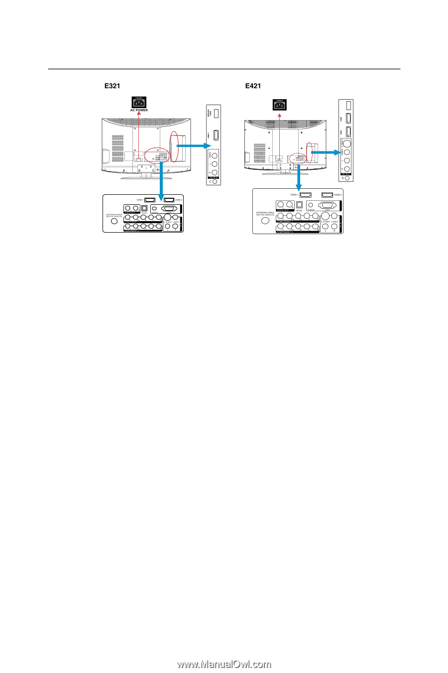
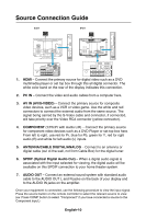
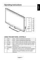
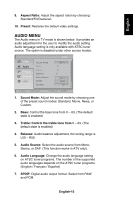
PORT SERVICE 4 3 PC IN PC IN Source Connection Guide AC POWER 1. HDMI - Connect the primary source for digital video such as a DVD multimedia player or set top box through this all digital connector. The white color band on the rear of the display indicates this connection. 2. PC IN - Connect the video and audio cables from a computer here. 3. AV IN (AV/S-VIDEO) - Connect the primary source for composite video devices, such as a VCR or video game. Use the white and red connectors to connect the external audio from the same source. The signal being carried by the S-Video cable and connector, if connected, will take priority over the Video RCA connector (yellow connector). 4. COMPONENT (Y/Pb/Pr with Audio L/R) - Connect the primary source for component video devices such as a DVD Player or set top box here. From left to right, use red for Pr, blue for Pb, green for Y, red for right audio (R) and white for left audio (L) inputs. 5. ANTENNA/CABLE DIGITAL/ANALOG - Connect to an antenna or digital cable (out of-the-wall, not from Cable Box) for the digital tuner. 6. SPDIF (Optical Digital Audio Out) - When a digital audio signal is associated with the input selected for viewing, the digital audio will be available on this SPDIF connection to your home theater system. 7. AUDIO OUT - Connect an external sound system with standard audio cable to the AUDIO OUT L and R jacks on the back of your display and to the AUDIO IN jacks on the amplifier. Once your equipment is connected, use the following procedure to view the input signal: Press the source button on the remote controller to select the relevant source to view. (ex: Press COMP button to select "Component" if you have connected a source to the Component input.) English-10
-
 1
1 -
2
-
3
-
4
-
5
-
6
-
7
-
 8
8 -
 9
9 -
 10
10 -
 11
11 -
 12
12 -
 13
13 -
 14
14 -
 15
15 -
 16
16 -
 17
17 -
 18
18 -
19
-
20
-
21
-
22
-
23
-
24
-
25
-
26
-
27
-
28
-
29
-
30
-
31
-
32
-
33
-
34
-
35
-
36
-
37
-
38
-
39
-
40
-
41
-
42
-
43
-
44
-
45
-
46
-
47
-
48
-
49
-
50
-
51
-
52
-
53
-
54
-
55
-
56
-
57
-
58
-
59
-
60
-
61
-
62
-
63
-
64
-
65
-
66
-
67
 |
 |