Netgear FS308 FS308 Installation Guide - Page 8
Connect Devices to the Switch, Ethernet specifications limit the cable length between your PC or - review
 |
View all Netgear FS308 manuals
Add to My Manuals
Save this manual to your list of manuals |
Page 8 highlights
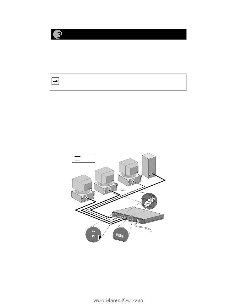
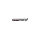
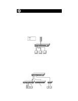
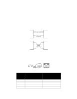
Connect Devices to the Switch Before connecting the switch, be sure you review "Applications" for information about determining the appropriate configuration for your networking needs. To connect the switch: 1. Connect the devices to the 10/100 Mbps ports on the switch, using Category 5 UTP cable and an RJ-45 plug. Note: Ethernet specifications limit the cable length between your PC or server and the switch to 328 feet (100 meters) in length. 2. Set the Normal/Uplink push button. 3. Set the FDX/AUTO toggle switches on the rear panel for the selected duplex mode (the default setting is AUTO). 4. Connect one end of the DC power adapter cable to the power outlet on the rear panel of the switch and the other end of the power adapter cable to the wall outlet. Refer to the following illustration when connecting the Model FS308 switch. Each of the preceding steps has a corresponding reference number in the illustration. Key 100 Mbps 10 Mbps RJ-45 connector 1 Normal/Uplink 1 8 FDX Duplex Mode AUTO 2 3 * Normal/Uplink ** 1 8 4 FDX Duplex Mode AUTO * Normal/Uplink push button set to the Normal position for connection to the server. ** For a typical configuration, set toggle switches to AUTO. For more information, refer to "FDX/AUTO Duplex Toggle Switches." 8935FA Model FS308 Fast Ethernet Switch Installation Guide
-
 1
1 -
2
-
 3
3 -
 4
4 -
 5
5 -
 6
6 -
 7
7 -
 8
8 -
 9
9 -
 10
10 -
 11
11 -
 12
12 -
 13
13 -
14
-
15
 |
 |