Netgear FS728TPv2 FS728TPv2 Hardware Installation Guide - Page 21
Step 4: Connecting Devices to the Switch, Desktop PC
 |
View all Netgear FS728TPv2 manuals
Add to My Manuals
Save this manual to your list of manuals |
Page 21 highlights
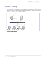
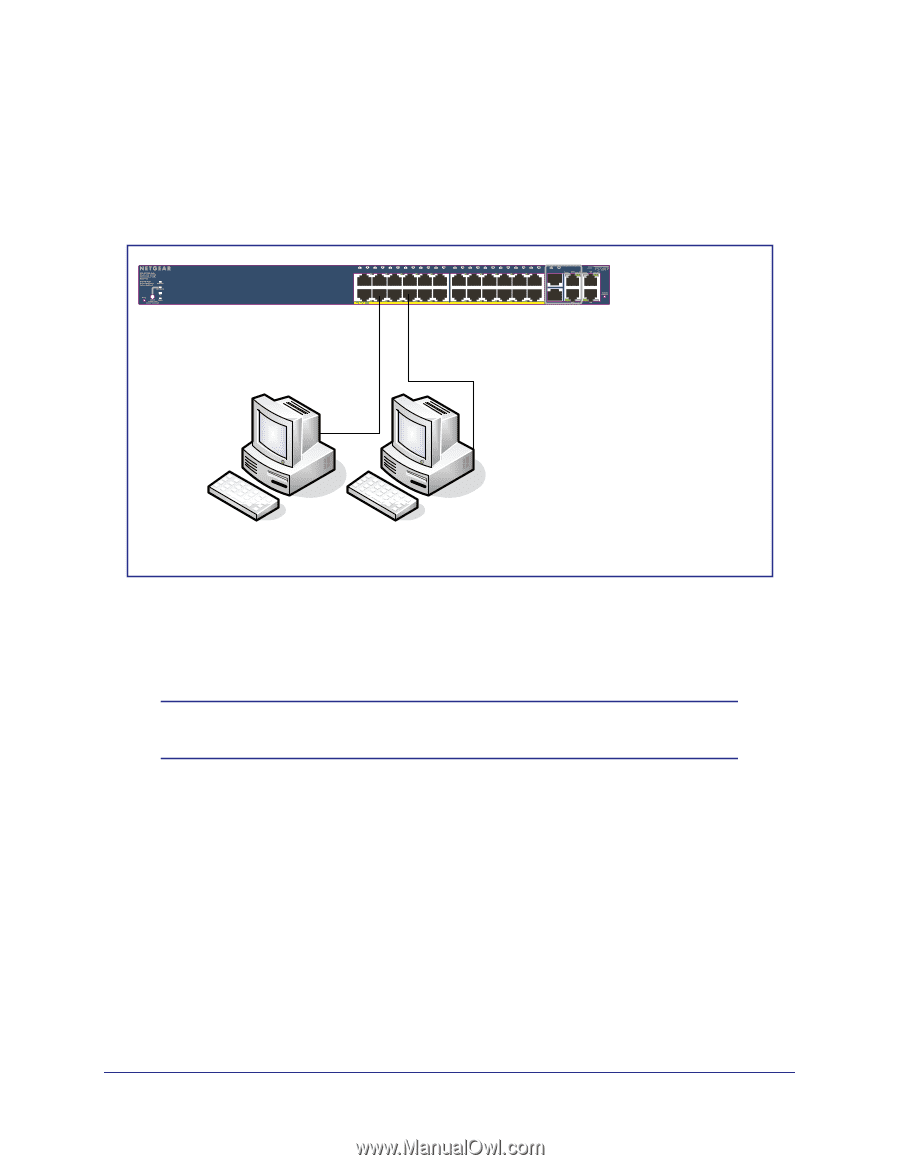
FS728TP Hardware Installation Guide Step 4: Connecting Devices to the Switch The following procedure describes how to connect PCs to the switch's RJ-45 ports. The FS728TP contains Auto Uplink technology, which allows the attaching of devices using either straight-through or crossover cables. ` ` Desktop PC Desktop PC Figure 5. Connecting Devices to the Switch Connect each PC to an RJ-45 network port on the Switch front panel (Figure 5). Use Category 5 (Cat5) Unshielded Twisted-Pair (UTP) cable terminated with an RJ-45 connector to make these connections. Note: Ethernet specifications limit the cable length between the switch and the attached device to 100m (328 ft.). Chapter 4: Installation | 21
-
 1
1 -
2
-
3
-
4
-
5
-
6
-
7
-
8
-
9
-
10
-
11
-
12
-
13
-
14
-
15
-
 16
16 -
 17
17 -
 18
18 -
 19
19 -
 20
20 -
 21
21 -
 22
22 -
 23
23 -
 24
24 -
 25
25 -
 26
26 -
27
-
28
-
29
-
30
-
31
-
32
-
33
-
34
-
35
-
36
 |
 |
Chapter 4:
Installation
|
21
FS728TP Hardware Installation Guide
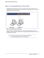
Step 4: Connecting Devices to the Switch
The following procedure describes how to connect PCs to the switch’s RJ-45 ports. The
FS728TP contains Auto Uplink technology, which allows the attaching of devices using either
straight-through or crossover cables.
Desktop PC
`
Desktop PC
`
Figure 5. Connecting Devices to the Switch
Connect each PC to an RJ-45 network port on the Switch front panel (
Figure
5
). Use
Category 5 (Cat5) Unshielded Twisted-Pair (UTP) cable terminated with an RJ-45 connector
to make these connections.
Note:
Ethernet specifications limit the cable length between the
switch and the attached device to 100m (328 ft.).