Netgear FS752TPS FS752TS Hardware manual
Netgear FS752TPS - ProSafe Smart Switch Manual
 |
View all Netgear FS752TPS manuals
Add to My Manuals
Save this manual to your list of manuals |
Netgear FS752TPS manual content summary:
- Netgear FS752TPS | FS752TS Hardware manual - Page 1
FS700TS (728TS, 752TS, 752TPS) Series Hardware Installation Guide NETGEAR, Inc. 4500 Great America Parkway Santa Clara, CA 95054 USA 202-10333-01 October 2007 - Netgear FS752TPS | FS752TS Hardware manual - Page 2
described in this document without notice. NETGEAR does not assume any liability that may occur due to the use or application of the product(s) or circuit layout(s) described herein. Certificate of the Manufacturer/Importer It is hereby certified that the FS700TS Smart Switch has been suppressed - Netgear FS752TPS | FS752TS Hardware manual - Page 3
with any other antenna or transmitter. FCC Declaration Of Conformity We NETGEAR, Inc., 4500 Great America Parkway, Santa Clara, CA 95054, declare under our sole responsibility that the model FS700TS Smart Switch with Gigabit Ports complies with Part 15 of FCC Rules. Operation is subject to - Netgear FS752TPS | FS752TS Hardware manual - Page 4
made to the product, unless expressly approved by NETGEAR, Inc., could void the user's right to operate the equipment. D Canadian Department of Communications Radio Interference Regulations This digital apparatus (FS700TS Smart Switch with Gigabit Ports) does not exceed the Class B limits for radio - Netgear FS752TPS | FS752TS Hardware manual - Page 5
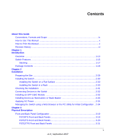
Guide Conventions, Formats and Scope ix How to Use This Manual x How to Print this Manual ...x Revision History ...xi Chapter 1 Introduction Overview ...1-13 Switch Features ...1-15 Stacking ...1-17 Package Contents ...1-18 Chapter 2 Installation Preparing the Site ...2-29 Installing the Switch - Netgear FS752TPS | FS752TS Hardware manual - Page 6
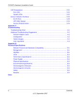
FS700TS Hardware Installation Guide LED Designations ...3-22 Port LEDs ...3-22 System LEDs ...3-24 Device Hardware Interfaces 3-25 RJ-45 Ports ...3-25 SFP GBIC Module 3-26 Factory Defaults Button 3-26 Appendix A Troubleshooting Troubleshooting Chart A-1 Additional Troubleshooting Suggestions - Netgear FS752TPS | FS752TS Hardware manual - Page 7
About This Guide Congratulations on the purchase of the NETGEAR Smart Switch. The NETGEAR® FS700TS Installation Manual describes how to install, configure and troubleshoot the smart switch. The information in this manual is intended for readers with intermediate computer and Internet skills. - Netgear FS752TPS | FS752TS Hardware manual - Page 8
Hardware Installation Guide Danger: This is a safety warning. Failure to take heed of this notice may result in personal injury or death. • Scope. This manual is written for the FS700TS according to these specifications: Product Version Manual Publication Date FS700TS Smart Switch September - Netgear FS752TPS | FS752TS Hardware manual - Page 9
icon in the upper left of the window. Tip: If your printer supports printing two pages on a single sheet of paper, you can save paper and printer ink by selecting this feature. • Printing the Full Manual. Use the Complete PDF Manual link at the top left of any page. - Click the Complete PDF - Netgear FS752TPS | FS752TS Hardware manual - Page 10
This Installation Guide is for the following NETGEAR FS700TS Smart Switches: • FS728TS - This product offers support for 24 ports of 10/100 BaseT, 2 ports of 10/100/1000 BaseT, and 2 GbE combo (Copper/Fiber) ports. • FS752TS - This product offers support for 48 ports of 10/100 BaseT, 2 ports of - Netgear FS752TPS | FS752TS Hardware manual - Page 11
FS700TS Hardware Installation Guide • Providing 10/100/1000 copper and fiber connectivity • The 2 10/100/1000 Base T ports are reserved for stacking, but can alternatively be used to provide additional bandwidth. The FS700TS Smart Switch also provides the benefit of administrative management with a - Netgear FS752TPS | FS752TS Hardware manual - Page 12
FS700TS Hardware Installation Guide Figure 1-1 Switch Features The following list identifies the key features of the NETGEAR Smart Switch. • 24/48 RJ-45 10/100 auto-sensing Giga switching ports. • 2-Port 10/100/1000M auto sensing Gigabit Ethernet switching ports. These ports are reserved for - Netgear FS752TPS | FS752TS Hardware manual - Page 13
Installation Guide The following SFP types are supported: • 1000Base-SX • 1000Base-LX • 100Base - FX • The devices support full Netgear Smart Switch -negotiating capabilities for all ports. • Auto Uplink™ on all ports to make the right connection. • Automatic address-learning function to build the - Netgear FS752TPS | FS752TS Hardware manual - Page 14
Installation Guide Stacking Stacking provides multiple switch management through a single point as if all stack masters are a single unit. All stack masters are accessed through a single IP address ports are supported in a stack During the Stacking setup, the switches Switch software is downloaded - Netgear FS752TPS | FS752TS Hardware manual - Page 15
contains the following: • NETGEAR Smart Switch • Rubber footpads for tabletop installation • Power cord • Rack-mount Kit for installing the switch in a 19-inch rack • Installation Guide • Smart Switch Resource CD with SmartWizard Discovery and User's manual • Warranty/Support Information Card If any - Netgear FS752TPS | FS752TS Hardware manual - Page 16
This chapter describes the installation procedures for your NETGEAR Smart Switch. Switch installation involves the following steps: "Preparing the Site" "Installing the Switch" "Checking the Installation" "Connecting Devices to the Switch" "Installing an SFP GBIC Module" "Installing Device as Stand - Netgear FS752TPS | FS752TS Hardware manual - Page 17
nearest source of electromagnetic noise, such as a photocopy machine. Installing the Switch The NETGEAR Smart Switch can be installed on a flat surface or in a standard 19-inch rack. Installing the Switch on a Flat Surface The switch ships with four self-adhesive rubber footpads. Stick one rubber - Netgear FS752TPS | FS752TS Hardware manual - Page 18
FS700TS Hardware Installation Guide 5. Tighten the screws with a #2 Phillips screwdriver to secure the switch in the rack. Figure 2-1 Note: Always install devices from the bottom of the to the top. This will prevent the rack from over balancing and toppling over. Checking the Installation Before - Netgear FS752TPS | FS752TS Hardware manual - Page 19
FS700TS Hardware Installation Guide Connecting Devices to the Switch The following procedure describes how to connect PCs to the switch's RJ-45 ports. The NETGEAR Smart Switch contains Auto Uplink™ technology, which allows you to attach devices using either straight-through or crossover cables. - Netgear FS752TPS | FS752TS Hardware manual - Page 20
designations are configured through automatic discovery. Manually changing the stacking configuration is through switch's web page once the device has been booted and is operational. For more information on stacking see the FS700TS Smart Switch User Guide. 2-33 v1.0, September 2007 Installation - Netgear FS752TPS | FS752TS Hardware manual - Page 21
information about managing the switch, see the Software Manual on the Smart Switch Resource CD. Note: When the device powers up, there is a default IP address already configured on the device. The default IP address is 192.168.0.239 and subnet mask 255.255.255.0. Installation v1.0, September 2007 - Netgear FS752TPS | FS752TS Hardware manual - Page 22
" • "FS752TS Front and Back Panels" • "FS752TPS Front and Back Panels" • "LED Designations" • "Device Hardware Interfaces" Front and Back Panel Configuration FS728TS Front and Back Panels The NETGEAR FS728TS Smart Switch is a 24/48-Port 10/100M + 4-Port 10/100/1000M smart stackable switch, with each - Netgear FS752TPS | FS752TS Hardware manual - Page 23
FS700TS Hardware Installation Guide • Recessed default reset button to restore the device back to the factory defaults. • Port LEDS • System LEDs Figure 3-2 illustrates the NETGEAR FS728TS Smart Switches back panel: Figure 3-2 The back panel contains the following: • A 100-240VAC/50-60 Hz universal - Netgear FS752TPS | FS752TS Hardware manual - Page 24
the NETGEAR FS752TS Smart Switches back panel: Figure 3-4 The back panel contains the following: • A 100-240VAC/50-60 Hz universal input, which is a standard AC power receptacle for accommodating the supplied power cord. FS752TPS Front and Back Panels The NETGEAR FS752TPS Smart Switch is a 48-Port - Netgear FS752TPS | FS752TS Hardware manual - Page 25
FS700TS Hardware Installation Guide Figure 3-6 illustrates the NETGEAR FS752TPS Smart Switch back panel: Figure 3-6 The back Port LEDs" • "System LEDs" Port LEDs The following table describes the port LED designations. Table 3-1. Port LEDS - Non-LED Devices Port 24/48-10/100M Ports One LED/Port - Netgear FS752TPS | FS752TS Hardware manual - Page 26
FS700TS Hardware Installation Guide Table 3-1. Port LEDS - Non-LED Devices (continued) Port LED Designation 4-Gigabits Copper Ports - Left LED Link/ACT/SPD Two LED's/Port on Jack LED: 2-SFP Ports - One LED/ Port Right LED Stack LED (Combo port group/ Copper port group): SFP Link/ACT LED • - Netgear FS752TPS | FS752TS Hardware manual - Page 27
Installation Guide Table 3-2. Port LEDs - PoE Devices (continued) Port LED Designation 24-10/100M Ports - One POE Indicate LED/POE LED/Port (PoE Mode) fault 4-Gigabits Copper Ports - Left LED Link/ACT/SPD Two LED's/Port on Jack LED: 2-SFP Ports - One LED/ SFP Link/ACT LED Port • Off - No PoE - Netgear FS752TPS | FS752TS Hardware manual - Page 28
"SFP GBIC Module" • "Factory Defaults Button" RJ-45 Ports RJ-45ports are auto-sensing ports. When inserting a cable into an RJ-45 port, the switch automatically ascertains the maximum speed (10 or 100 or 1000 Mbps) and duplex mode (half- or full-duplex) of the attached device. All ports support only - Netgear FS752TPS | FS752TS Hardware manual - Page 29
SFP GBIC module. Factory Defaults Button The Smart Switch has a Factory default button to enable clearing the current configuration and returning the device back to the factory settings. This removes all settings, including the password, VLAN settings and port configurations. Physical Description - Netgear FS752TPS | FS752TS Hardware manual - Page 30
troubleshooting the NETGEAR Smart Switch. The topics include the following: • "Troubleshooting Chart" • "Additional Troubleshooting Suggestions" Troubleshooting Chart The following table lists symptoms, causes, and solutions of possible problems. Table A-1. Troubleshooting port at both the switch - Netgear FS752TPS | FS752TS Hardware manual - Page 31
of the installation do not exceed the Ethernet limitations. Switch Integrity If required, verify the integrity of the switch by resetting the switch. To reset the switch, disconnect the AC power from the switch and then reconnect AC source. If the problem continues, contact NETGEAR technical support - Netgear FS752TPS | FS752TS Hardware manual - Page 32
Hardware Installation Guide Auto-negotiation The RJ-45 ports negotiate the correct duplex mode and speed if the device at the other end of the link supports auto-negotiation. If the device does not support auto negotiation, the switch only determines the speed correctly and the duplex mode defaults - Netgear FS752TPS | FS752TS Hardware manual - Page 33
IEEE 802.3af (DTE Power via MDI) IEEE 802.1x IEEE 802.1D Management IEEE 802.1Q Static VLAN (Up to 128 ranging from 2 to 4K) IEEE 802.1p Class of Service (CoS) Port-based QoS (options High/Normal) Port Trunking LACP Interface 24/48 RJ-45 connectors for 10Base-T,100Base-TX (Auto Uplink™ on all - Netgear FS752TPS | FS752TS Hardware manual - Page 34
FS700TS Hardware Installation Guide LEDs Per port (Gigabit): Link/Activity, Speed, Stack (for stacking-enabled ports) Per device: Power, Stack Master, Unit Number Performance Specifications Forwarding modes: Store-and-forward Bandwidth: 12.8 Gbps (for FS728TS) / 17.6 Gbps) Address database size: - Netgear FS752TPS | FS752TS Hardware manual - Page 35
FS700TS Hardware Installation Guide VCCI Class A C-Tick Electromagnetic Immunity EN 55022 (CISPR 22), Class A Safety CE mark, commercial UL listed (UL 1950) / CUL IEC950 / EN60950 Modules AGM731F 1000Base-SX - Netgear FS752TPS | FS752TS Hardware manual - Page 36
the Installation 4-15 Class of Service 1-2 Combo Port 2-10 Combo Ports 1-2 Connecting Devices to the Switch 4-16 Copper 1-1 Crossover 2-9 D Default IP Address 4-18 Default Reset Button 2-5, 2-7 Device Hardware Interfaces 2-9 Duplex Mode 2-9 E Example of Desktop Switching 3-12 F Factory Default - Netgear FS752TPS | FS752TS Hardware manual - Page 37
Requirements 4-13 Small Form-factor Pluggable (SFP) 1-2 Smart Switch Resource CD 1-4 SmartWizard Discovery 1-2 Straight-through 2-9 Support Information Card 1-4 System LEDs 2-9 T Temperature 4-14 Traffic Control 1-1 Troubleshooting Chart A-19 U User Intervention 2-10 Index-2 v1.0, September 2007 - Netgear FS752TPS | FS752TS Hardware manual - Page 38
User's Manual 1-4 UTP 4-16 V Ventilation 4-14 VLAN 1-1 W Warranty 1-4 Web-based Graphical User Interface 1-1 GS700TP Hardware Installation Guide v1.0, September 2007 Index-3 - Netgear FS752TPS | FS752TS Hardware manual - Page 39
GS700TP Hardware Installation Guide Index-4 v1.0, September 2007
-
 1
1 -
 2
2 -
 3
3 -
 4
4 -
 5
5 -
 6
6 -
 7
7 -
8
-
9
-
10
-
11
-
12
-
13
-
14
-
15
-
16
-
17
-
18
-
19
-
20
-
21
-
22
-
23
-
24
-
25
-
26
-
27
-
28
-
29
-
30
-
31
-
32
-
33
-
34
-
35
-
36
-
37
-
38
-
39
 |
 |
202-10333-01
October 2007
NETGEAR
, Inc.
4500 Great America Parkway
Santa Clara, CA 95054 USA
FS700TS (728TS, 752TS,
752TPS) Series Hardware
Installation Guide