Netgear FSM7226RS FSM7226RS / FSM7250RS Hardware Installation Guide - Page 24
Connecting Equipment to the Switch, RJ-45 Ports
 |
UPC - 606449059915
View all Netgear FSM7226RS manuals
Add to My Manuals
Save this manual to your list of manuals |
Page 24 highlights
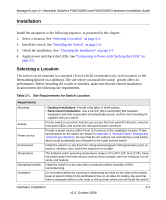
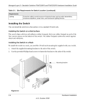
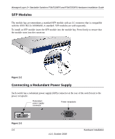
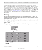
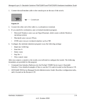
Managed Layer 2+ Stackable Switches FSM7226RS and FSM7250RS Hardware Installation Guide 3. Connect each switch to the next in a cascade to build the backplane of the stack. Finally, connect the last switch in the stack to the first switch, to close the ring and provide redundancy and resiliency to the stack. The switches automatically select the master switch in the stack. 4. To use the console and Command Line Interface (CLI), use a serial cable to connect the console to the master switch. This single console connection lets you manage all the switches in the stack. For information about working with the CLI, see the Command Line Interface Reference for the ProSafe 7200RS Series Layer-2 Stackable Switches on the Resource CD that shipped with your product. Connecting Equipment to the Switch You can connect devices, a Gigabit Ethernet module, and/or a console to the switch. RJ-45 Ports The switch uses Auto Uplink technology, which enables you to attach devices using either straight-through or crossover cables. Use a Category 5 (Cat5) unshielded twisted-pair (UTP) cable terminated with an RJ-45 connector. Note: Ethernet specifications limit the cable length between the switch and the attached device to 328 feet (100 meters). Connecting a Console to the Switch After you install the switch and apply power, you can connect to it with a terminal or workstation. You can use the Command Line Interface (CLI) to identify the IP address. If you are stacking switches, see "Stacking" on page 2-7. To use a console you need the following items: • VT100/ANSI terminal, or a Windows PC, Apple Macintosh PC, or UNIX workstation. • Null-modem cable with 9-pin connectors on each end (shipped with the product). To connect a console to the switch: 2-8 Hardware Installation v1.0, October 2008
-
 1
1 -
2
-
3
-
4
-
5
-
6
-
7
-
8
-
9
-
10
-
11
-
12
-
13
-
14
-
15
-
16
-
17
-
18
-
 19
19 -
 20
20 -
 21
21 -
 22
22 -
 23
23 -
 24
24 -
 25
25 -
 26
26 -
 27
27 -
 28
28 -
 29
29 -
30
-
31
-
32
-
33
-
34
 |
 |
