Netgear FVS114 FVS114 Reference Manual - Page 104
FVS114 Scenario 1: FVS114 to Gateway B IKE and VPN Policies - review
 |
UPC - 606449040494
View all Netgear FVS114 manuals
Add to My Manuals
Save this manual to your list of manuals |
Page 104 highlights
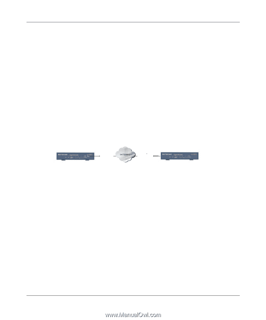
Reference Manual for the ProSafe VPN Firewall FVS114 The IKE Phase 2 parameters used in Scenario 1 are: • TripleDES • SHA-1 • ESP tunnel mode • MODP group 2 (1024 bits) • Perfect forward secrecy for rekeying • SA lifetime of 3600 seconds (one hour) with no kilobytes rekeying • Selectors for all IP protocols, all ports, between 10.5.6.0/24 and 172.23.9.0/24, using IPv4 subnets FVS114 Scenario 1: FVS114 to Gateway B IKE and VPN Policies Note: This scenario assumes all ports are open on the FVS114. You can verify this by reviewing the security settings as seen in the Figure 4-2 on page 4-4. 10.5.6.1/24 LAN IP Gateway A FVS114 Scenario 1 14.15.16.17 WAN IP 22.23.24.25 WAN IP Gateway B FVS114 Figure 6-6: LAN to LAN VPN access from an FVS114 to an FVS114 172.23.9.1/24 LAN IP Use this scenario illustration and configuration screens as a model to build your configuration. 1. Log in to the FVS114 labeled Gateway A as in the illustration. Log in at the default address of http://192.168.0.1 with the default user name of admin and default password of password, or using whatever password and LAN address you have chosen. 2. Configure the WAN (Internet) and LAN IP addresses of the FVS114. a. From the main menu Setup section, click the Basic Setup link to go back to the Basic Settings menu. 6-16 Advanced Virtual Private Networking 202-10098-01, April 2005
-
 1
1 -
2
-
3
-
4
-
5
-
6
-
7
-
8
-
9
-
10
-
11
-
12
-
13
-
14
-
15
-
16
-
17
-
18
-
19
-
20
-
21
-
22
-
23
-
24
-
25
-
26
-
27
-
28
-
29
-
30
-
31
-
32
-
33
-
34
-
35
-
36
-
37
-
38
-
39
-
40
-
41
-
42
-
43
-
44
-
45
-
46
-
47
-
48
-
49
-
50
-
51
-
52
-
53
-
54
-
55
-
56
-
57
-
58
-
59
-
60
-
61
-
62
-
63
-
64
-
65
-
66
-
67
-
68
-
69
-
70
-
71
-
72
-
73
-
74
-
75
-
76
-
77
-
78
-
79
-
80
-
81
-
82
-
83
-
84
-
85
-
86
-
87
-
88
-
89
-
90
-
91
-
92
-
93
-
94
-
95
-
96
-
97
-
98
-
 99
99 -
 100
100 -
 101
101 -
 102
102 -
 103
103 -
 104
104 -
 105
105 -
 106
106 -
 107
107 -
 108
108 -
 109
109 -
110
-
111
-
112
-
113
-
114
-
115
-
116
-
117
-
118
-
119
-
120
-
121
-
122
-
123
-
124
-
125
-
126
-
127
-
128
-
129
-
130
-
131
-
132
-
133
-
134
-
135
-
136
-
137
-
138
-
139
-
140
-
141
-
142
-
143
-
144
-
145
-
146
-
147
-
148
-
149
-
150
-
151
-
152
-
153
-
154
-
155
-
156
-
157
-
158
-
159
-
160
-
161
-
162
-
163
-
164
-
165
-
166
-
167
-
168
-
169
-
170
-
171
-
172
-
173
-
174
-
175
-
176
-
177
-
178
-
179
-
180
-
181
-
182
-
183
-
184
-
185
-
186
-
187
-
188
-
189
-
190
-
191
-
192
-
193
-
194
-
195
-
196
-
197
-
198
-
199
-
200
-
201
-
202
-
203
-
204
-
205
-
206
-
207
-
208
-
209
-
210
-
211
-
212
 |
 |