Netgear FWG114Pv2 FWG114Pv2 Reference Manual - Page 269
Test the VPN Connection, VPN Policies, Enable, Apply
 |
View all Netgear FWG114Pv2 manuals
Add to My Manuals
Save this manual to your list of manuals |
Page 269 highlights
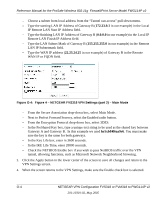
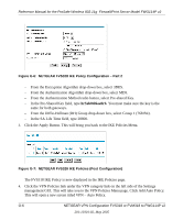
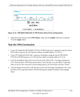
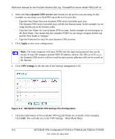
Reference Manual for the ProSafe Wireless 802.11g Firewall/Print Server Model FWG114P v2 Figure G-10: NETGEAR FWG114P v2 VPN Policies Menu (Post Configuration) 6. When the screen returns to the VPN Policies, make sure the Enable check box is selected. Click the Apply button. Test the VPN Connection 1. From a PC behind the NETGEAR FVS318 or FVM318 gateway A attempt to ping the remote FWG114P v2 gateway B LAN Interface address (example address 172.23.9.1). 2. From a PC behind the FWG114P v2 gateway B attempt to ping the remote NETGEAR FVS318 or FVM318 gateway A LAN Interface address (example address 10.5.6.1). 3. Click the Broadband Status link on the left side of the FWG114P v2 Settings management GUI. Click the Show VPN Status button below. This will take you to the IPSec Connection Status Screen. If the connection is functioning properly, the State fields will show "Estab." 4. Click the Router Status link on the left side of the FVS318 Settings management GUI. Click the Show VPN Logs button below. NETGEAR log files should be similar to the example below. NETGEAR VPN Configuration FVS318 or FVM318 to FWG114P v2 G-9 201-10301-02, May 2005
-
 1
1 -
2
-
3
-
4
-
5
-
6
-
7
-
8
-
9
-
10
-
11
-
12
-
13
-
14
-
15
-
16
-
17
-
18
-
19
-
20
-
21
-
22
-
23
-
24
-
25
-
26
-
27
-
28
-
29
-
30
-
31
-
32
-
33
-
34
-
35
-
36
-
37
-
38
-
39
-
40
-
41
-
42
-
43
-
44
-
45
-
46
-
47
-
48
-
49
-
50
-
51
-
52
-
53
-
54
-
55
-
56
-
57
-
58
-
59
-
60
-
61
-
62
-
63
-
64
-
65
-
66
-
67
-
68
-
69
-
70
-
71
-
72
-
73
-
74
-
75
-
76
-
77
-
78
-
79
-
80
-
81
-
82
-
83
-
84
-
85
-
86
-
87
-
88
-
89
-
90
-
91
-
92
-
93
-
94
-
95
-
96
-
97
-
98
-
99
-
100
-
101
-
102
-
103
-
104
-
105
-
106
-
107
-
108
-
109
-
110
-
111
-
112
-
113
-
114
-
115
-
116
-
117
-
118
-
119
-
120
-
121
-
122
-
123
-
124
-
125
-
126
-
127
-
128
-
129
-
130
-
131
-
132
-
133
-
134
-
135
-
136
-
137
-
138
-
139
-
140
-
141
-
142
-
143
-
144
-
145
-
146
-
147
-
148
-
149
-
150
-
151
-
152
-
153
-
154
-
155
-
156
-
157
-
158
-
159
-
160
-
161
-
162
-
163
-
164
-
165
-
166
-
167
-
168
-
169
-
170
-
171
-
172
-
173
-
174
-
175
-
176
-
177
-
178
-
179
-
180
-
181
-
182
-
183
-
184
-
185
-
186
-
187
-
188
-
189
-
190
-
191
-
192
-
193
-
194
-
195
-
196
-
197
-
198
-
199
-
200
-
201
-
202
-
203
-
204
-
205
-
206
-
207
-
208
-
209
-
210
-
211
-
212
-
213
-
214
-
215
-
216
-
217
-
218
-
219
-
220
-
221
-
222
-
223
-
224
-
225
-
226
-
227
-
228
-
229
-
230
-
231
-
232
-
233
-
234
-
235
-
236
-
237
-
238
-
239
-
240
-
241
-
242
-
243
-
244
-
245
-
246
-
247
-
248
-
249
-
250
-
251
-
252
-
253
-
254
-
255
-
256
-
257
-
258
-
259
-
260
-
261
-
262
-
263
-
 264
264 -
 265
265 -
 266
266 -
 267
267 -
 268
268 -
 269
269 -
 270
270 -
 271
271 -
 272
272 -
 273
273 -
 274
274 -
275
-
276
-
277
-
278
-
279
-
280
-
281
-
282
-
283
-
284
-
285
-
286
-
287
-
288
-
289
-
290
-
291
-
292
-
293
-
294
-
295
-
296
 |
 |