Netgear GS504 GS504 Installation Guide - Page 4
Product Illustration
 |
View all Netgear GS504 manuals
Add to My Manuals
Save this manual to your list of manuals |
Page 4 highlights
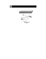
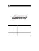
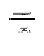
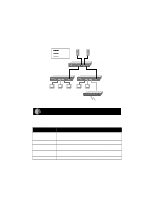
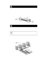
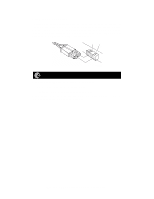
Product Illustration Front Panel The front panel of the Model GS504 switch contains the following LEDs that correspond to each network port: Activity (Rx/Tx) and FDX (full-duplex)/ Collision. Each fiber network port has its own Link LED (located to the right of each 1000 Mbps port). Front Panel of the Model GS504 Switch Activity LEDs Fiber network ports 4PORT 10/100Mbps Gigabit Fiber Switch Power Activity 1234 Green=FDX, Yellow=Col 1 Tx Rx Link 2 Tx Rx Link Ethernet MODEL GS504SX 3 Tx Rx Link 4 Tx Rx Link FDX/Collision LED Power LED Link LED 9318FA LEDs The table below describes the activity of the LEDs. Label Power FDX/Col Color Green Green Activity On Off On Off Description Power is supplied to the switch. Power is disconnected. The port is operating in full-duplex mode. The port is operating in half-duplex mode. Activity Link Yellow Green Green Blinking Blinking On Off Data collisions are occurring on the port. In a fullduplex environment, there is no collision. In a halfduplex environment, some collisions are normal. Packet transmission or reception is occurring on the port. A valid 1000 Mbps link is established on the port. A link is not established on the port. Model GS504 4-Port Gigabit Switch Installation Guide
-
 1
1 -
 2
2 -
 3
3 -
 4
4 -
 5
5 -
 6
6 -
 7
7 -
 8
8 -
 9
9 -
 10
10 -
11
-
12
-
13
 |
 |