Netgear GS516TP Hardware Installation Guide
Netgear GS516TP Manual
 |
View all Netgear GS516TP manuals
Add to My Manuals
Save this manual to your list of manuals |
Netgear GS516TP manual content summary:
- Netgear GS516TP | Hardware Installation Guide - Page 1
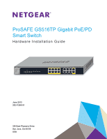
ProSAFE GS516TP Gigabit PoE/PD Smart Switch Hardware Installation Guide June 2013 202-11260-01 350 East Plumeria Drive San Jose, CA 95134 USA - Netgear GS516TP | Hardware Installation Guide - Page 2
. To register your product, get the latest product updates, get support online, or for more information about the topics covered in this manual, visit the support website at http://support.netgear.com. Phone (US & Canada only): 1-888-NETGEAR Phone (Other Countries): Check the list of phone numbers - Netgear GS516TP | Hardware Installation Guide - Page 3
GS516TP Front Panel and Back Panel Configuration 11 LED Designations 12 Port LEDs 12 System LEDs 13 Device Hardware Interfaces 13 RJ-45 Ports 13 Reset Button 14 Factory Defaults Utility22 Appendix A Troubleshooting Troubleshooting Chart 25 Additional Troubleshooting Suggestions 25 Network - Netgear GS516TP | Hardware Installation Guide - Page 4
GS516TP Gigabit Smart Switch Autonegotiation 26 Appendix B Technical Specifications Network Protocol and Standards Compatibility 27 Management 27 Interface 28 LEDs 28 Performance Specifications 28 Power Supply - Netgear GS516TP | Hardware Installation Guide - Page 5
16 twisted-paired ports that support nonstop 10/100/1000 networks. To simplify installation, the switch is shipped ready for use out of the box. The installation guide describes how to install and power on the GS516TP Gigabit Smart Switch. The information in this manual is intended for readers with - Netgear GS516TP | Hardware Installation Guide - Page 6
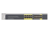
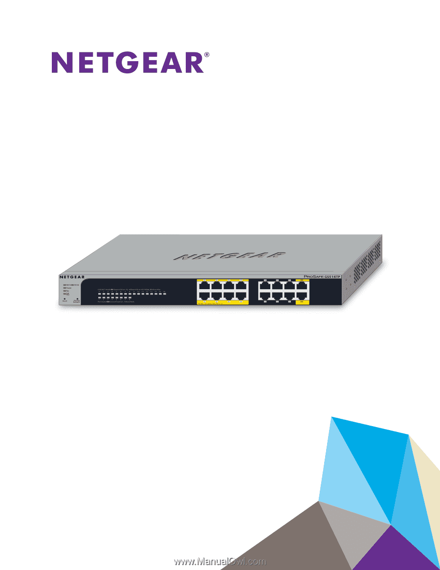
The NETGEAR GS516TP Gigabit Smart Switch provides 16 twisted-pair ports that support nonstop VLAN for traffic control • Port trunking for increased bandwidth • Class of Service Gigabit Ethernet switching ports. • The first eight ports are PoE (Power over Ethernet) PSE ports providing up to 15.4W - Netgear GS516TP | Hardware Installation Guide - Page 7
GS516TP Gigabit Smart Switch - IEEE802.3af (DTE Power via MDI) - IEEE802.3at (DTE Power via . Power LED, FAN Status LED, Max PoE LED, and LEDs for each port. • Internal open frame power supply. • Standard NETGEAR 5xx series chassis. • NETGEAR Green product series power-saving features: - Automatic - Netgear GS516TP | Hardware Installation Guide - Page 8
Verify that the package contains the following: • GS516TP Gigabit Smart Switch • Rubber footpads for tabletop installation • Rack-mounting kit • Power cord • Installation guide • Smart switch resource CD with NETGEAR Smart Control Center and user's manual If any item is missing or damaged, contact - Netgear GS516TP | Hardware Installation Guide - Page 9
GS516TP Gigabit Smart Switch Introduction 9 - Netgear GS516TP | Hardware Installation Guide - Page 10
2. Physical Description This chapter describes the GS516TP Gigabit PoE Smart Switch hardware features. Topics include: • GS516TP Front Panel and Back Panel Configuration • LED Designations • Device Hardware Interfaces 2 10 - Netgear GS516TP | Hardware Installation Guide - Page 11
GS516TP Gigabit PoE Smart Switch GS516TP Front Panel and Back Panel Configuration The smart switch panel of the smart switch. PD15, PD16, Power, Link/ACT LEDs Fan, PoE Max LEDs Factory Defaults button Reset button PoE Status LEDs Figure 1. Front panel The front panel contains the following: • 16 - Netgear GS516TP | Hardware Installation Guide - Page 12
GS516TP Gigabit PoE Smart Switch The following figure illustrates the smart switch back panel of the smart switch. Port LEDs The following table describes the RJ-45 port Link/ACT and PoE port status LED designations. Table 2-1. Port LEDs LED Designation Link/ACT LED mode for copper ports 1- - Netgear GS516TP | Hardware Installation Guide - Page 13
GS516TP Gigabit PoE Smart Switch System LEDs The following table describes the system LED designations. Table 2-2. System LEDs LED Power Fan Max PoE mode (half-duplex or full-duplex) of the attached device. All ports support only an unshielded twisted-pair (UTP) cable terminated with an 8-pin RJ - Netgear GS516TP | Hardware Installation Guide - Page 14
remove the current configuration and return the device to its factory settings. When you press the Factory Defaults button, all settings including the password, VLAN settings, and port configurations are removed. To operate the Factory Defaults button, insert a device such as a paper clip into the - Netgear GS516TP | Hardware Installation Guide - Page 15
3. Applications Your smart switch is designed to provide flexibility in configuring your network connections. It can be used as your only network traffic-distribution device or with 10 Mbps, 100 Mbps, and 1000 Mbps hubs and switches. This chapter describes the applications of the smart switch. - Netgear GS516TP | Hardware Installation Guide - Page 16
GS516TP Gigabit Smart Switch Desktop Switching The smart switch can be used as a desktop switch to build a small network that enables users to have 1000 Mbps - Netgear GS516TP | Hardware Installation Guide - Page 17
GS516TP Gigabit Smart Switch Backbone Switching You can use the smart switch as a backbone switch in a small network that gives users high-speed access to servers and other network devices. Figure 4. Backbone switching Applications 17 - Netgear GS516TP | Hardware Installation Guide - Page 18
4. Installation 4 This chapter describes the installation procedures for your GS516TP Gigabit Smart Switch. Switch installation involves the procedures described in the following sections: • Prepare the Site • Install the Switch • Check the Installation • Connect Devices to - Netgear GS516TP | Hardware Installation Guide - Page 19
GS516TP Gigabit Smart Switch Prepare the Site Before you install the switch, Provide a power connection cord. For information about power specifications for the switch, see Appendix A, Troubleshooting. Ensure that the AC outlet is not controlled by a wall switch, which can accidentally turn - Netgear GS516TP | Hardware Installation Guide - Page 20
GS516TP Gigabit Smart Switch 2. Insert the screws provided in the rack-mount kit through each bracket and into the bracket mounting holes in the switch. 3. Tighten - Netgear GS516TP | Hardware Installation Guide - Page 21
GS516TP Gigabit Smart Switch Connect Devices to the Switch The following procedure describes how to connect computers to the switch's RJ-45 ports. The switch contains - Netgear GS516TP | Hardware Installation Guide - Page 22
GS516TP is good. If this does not resolve the problem, see to Appendix A, Troubleshooting. Apply DC Power Through PD Ports 15 or However, the management software enables the setup of VLAN and trunking features and also improves the efficiency of manual on the smart switch resource CD. Installation 22 - Netgear GS516TP | Hardware Installation Guide - Page 23
GS516TP Gigabit Smart Switch Note: The switch is configured with a default IP address of 192.168.0.239 and a subnet mask of 255.255.255.0. Installation 23 - Netgear GS516TP | Hardware Installation Guide - Page 24
A. Troubleshooting A This chapter provides information about troubleshooting the NETGEAR Smart Switch. Topics include the following: • Troubleshooting Chart • Additional Troubleshooting Suggestions 24 - Netgear GS516TP | Hardware Installation Guide - Page 25
GS516TP Gigabit Smart Switch Troubleshooting Chart The following table lists symptoms and causes of and solutions to possible problems. Table A-4. Troubleshooting Chart Symptom Cause Solution Power LED is off. No power is received. Check the power cord connections and the connected device. - Netgear GS516TP | Hardware Installation Guide - Page 26
Integrity If necessary, verify the integrity of the switch by resetting the switch. To reset the switch, remove the AC power from the switch and then reapply AC power. If the problem continues, contact NETGEAR technical support. Autonegotiation The RJ-45 ports negotiate the correct duplex mode - Netgear GS516TP | Hardware Installation Guide - Page 27
, dynamic VLAN assignment • IEEE 802.1AB LLDP, LLDP-MED • SNMP v1, v2c, and v3 • TFTP, HTTP, and HTTPS • Port mirroring (RX, TX, and both) • IGMP snooping v1, v2, v3 • IEEE 802.1p Class of Service (CoS) • SNTP (Simple Network Time Protocol) three servers. Disabled by default. • Jumbo frame support - Netgear GS516TP | Hardware Installation Guide - Page 28
voice VLAN • Protected ports • Time-based PoE management • Syslog • Smart Control Center Discovery program auto discovers devices and sets system configuration to each switch. • Configuration backup and restore (easy to configure more than one switch) • Password access control • Firmware upgradeable - Netgear GS516TP | Hardware Installation Guide - Page 29
GS516TP Gigabit Smart Switch - 132,722 hours (~15.15 years) at 55°C Power Supply • AC voltage: 100-240 V • Frequency: 50/60 Hz • Amperage (maximum): 1.8A Physical - Netgear GS516TP | Hardware Installation Guide - Page 30
firmware limits operation to only the channels allowed in a particular Region or Country. Therefore, all options described in this user's guide not contain any user serviceable components and is to or transmitter. FCC Declaration Of Conformity We, NETGEAR, Inc., 350 East Plumeria Drive, San Jose - Netgear GS516TP | Hardware Installation Guide - Page 31
not installed and used in accordance with the instructions, may cause harmful interference to radio communications. for help. Modifications made to the product, unless expressly approved by NETGEAR, Inc., could void the user's right to operate the equipment. du Canada. Notification of Compliance 31
-
 1
1 -
 2
2 -
 3
3 -
 4
4 -
 5
5 -
 6
6 -
 7
7 -
8
-
9
-
10
-
11
-
12
-
13
-
14
-
15
-
16
-
17
-
18
-
19
-
20
-
21
-
22
-
23
-
24
-
25
-
26
-
27
-
28
-
29
-
30
-
31
 |
 |
350 East Plumeria Drive
San Jose, CA 95134
USA
June 2013
202-11260-01
ProSAFE GS516TP Gigabit PoE/PD
Smart Switch
Hardware Installation Guide