Netgear GS516TP Hardware Installation Guide - Page 13
System LEDs, Device Hardware Interfaces, RJ-45 Ports
 |
View all Netgear GS516TP manuals
Add to My Manuals
Save this manual to your list of manuals |
Page 13 highlights
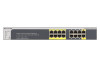
GS516TP Gigabit PoE Smart Switch System LEDs The following table describes the system LED designations. Table 2-2. System LEDs LED Power Fan Max PoE LED PD15 and PD16 Designation • Solid green. The device is powered on; runtime code is operating. • Blinking yellow. The device is in the boot stage. • Off. Power is not supplied to the device. • Solid yellow. The fan has experienced a failure. • Off. The fan is operating normally. • Solid yellow. Less than 7W of PoE power is available. • Blinking yellow. The PoE Max LED was lit within the previous two minutes. • Off. At least 7W of PoE power is available. • Off. No PSE device is connected to ports 15 or 16. • Solid green. An 802.3at PSE device is connected to ports 15 or 16. • Solid yellow. An 802.3af PSE device is connected to ports 15 or 16. Device Hardware Interfaces The following sections describe the ports and buttons found on the smart switch. RJ-45 Ports RJ-45 ports are AutoSensing ports. When you insert a cable into an RJ-45 port, the switch automatically ascertains the maximum speed (10, 100, or 1000 Mbps) and duplex mode (half-duplex or full-duplex) of the attached device. All ports support only an unshielded twisted-pair (UTP) cable terminated with an 8-pin RJ-45 plug. To simplify the procedure for attaching devices, all RJ-45 ports support Auto Uplink. This technology allows attaching devices to the RJ-45 ports with either straight-through or crossover cables. When you insert a cable into the switch's RJ-45 port, the switch automatically does the following: • Senses whether the cable is a straight-through or crossover cable. • Determines whether the link to the attached device requires a "normal" connection (such as when you are connecting the port to a computer) or an "uplink" connection (such as when you are connecting the port to a router, switch, or hub). • Configures the RJ-45 port to enable communications with the attached device, without requiring user intervention. In this way, the Auto Uplink technology compensates for setting uplink connections, while eliminating concern about whether to use crossover or straight-through cables when you are attaching devices. Physical Description 13
-
 1
1 -
2
-
3
-
4
-
5
-
6
-
7
-
 8
8 -
 9
9 -
 10
10 -
 11
11 -
 12
12 -
 13
13 -
 14
14 -
 15
15 -
 16
16 -
 17
17 -
 18
18 -
19
-
20
-
21
-
22
-
23
-
24
-
25
-
26
-
27
-
28
-
29
-
30
-
31
 |
 |
