Netgear GS724Tv2 GS724Tv2 Hardware manual - Page 14
Step 3: Checking the Installation, Step 4: Connecting Devices to the Switch, Step 5: Installing an
 |
View all Netgear GS724Tv2 manuals
Add to My Manuals
Save this manual to your list of manuals |
Page 14 highlights
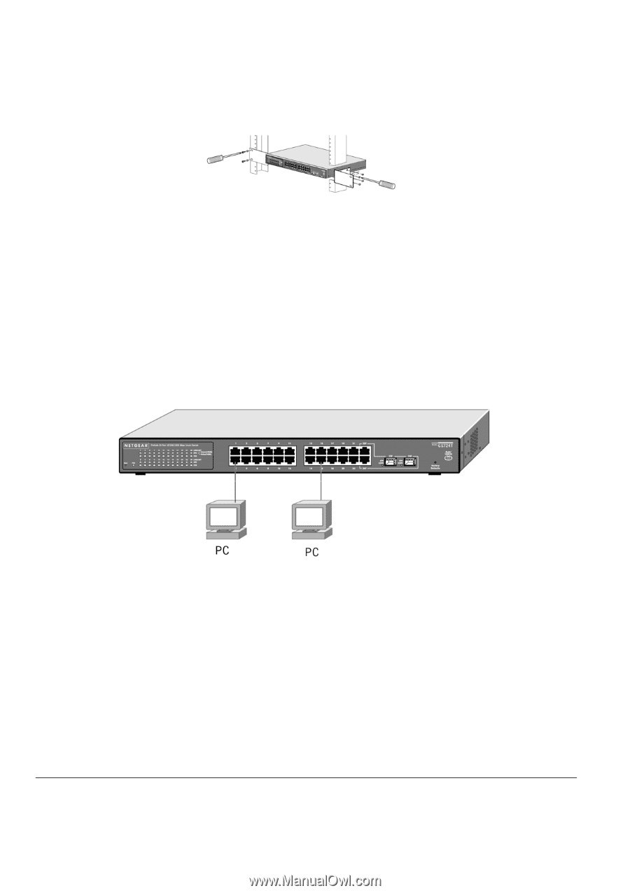
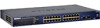
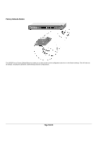
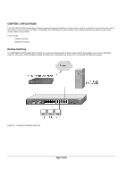
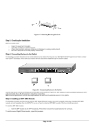
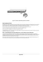
Figure 4-1. Attaching Mounting Brackets Step 3: Checking the Installation Before you apply power: o Inspect the equipment thoroughly. o Verify that all cables are installed correctly. o Check cable routing to make sure cables are not damaged or creating a safety hazard. o Be sure all equipment is mounted properly and securely. Step 4: Connecting Devices to the Switch The following procedure describes how to connect devices to the switch's RJ-45 ports. Your NETGEAR GS724T Gigabit Smart Switch contains Auto Uplink™ technology, which allows you to attach devices using either straight-through or crossover cables. Figure 4-2. Connecting Devices to the Switch Connect each device to an RJ-45 network port on the switch's front panel (see Figure 4-4). Use Category 5 (Cat5) unshielded twisted-pair (UTP) cable terminated with an RJ-45 connector to make these connections. Note: Ethernet specifications limit the cable length between the switch and the attached device to 100 m (328 ft). Step 5: Installing an SFP GBIC Module The following procedure describes how to install an SFP Gigabit Ethernet module in the switch's Gigabit module bays. Standard SFP GBIC modules are sold separately from the GS724T. If you do not want to install an SFP GBIC module at this time, skip this procedure. To install an SFP GBIC module: o Insert the SFP module into the SFP module bay. Press firmly to ensure the module seats into the connector. To install a second Gigabit Ethernet module, repeat this procedure Page 14 of 20
-
 1
1 -
2
-
3
-
4
-
5
-
6
-
7
-
8
-
 9
9 -
 10
10 -
 11
11 -
 12
12 -
 13
13 -
 14
14 -
 15
15 -
 16
16 -
 17
17 -
 18
18 -
 19
19 -
20
 |
 |