Netgear GS724Tv2 GS724Tv2 Hardware manual - Page 9
SFP GBIC Module, LED Descriptions, Reset Button
 |
View all Netgear GS724Tv2 manuals
Add to My Manuals
Save this manual to your list of manuals |
Page 9 highlights
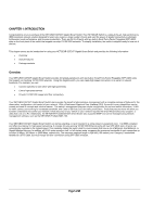
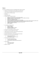
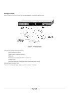
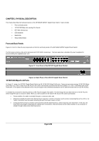
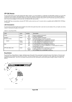
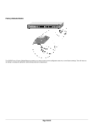
SFP GBIC Module The two module bays accommodate standard SFP GBIC modules, such as the AGM731F or AGM732F from NETGEAR, allowing you to have fiber connections on your network. The module bays are combo ports, sharing a connection with the last two RJ-45 ports, port 23T and 24T. Being a combo port, only one type of connection can be active at any given time. For example, both port 23T and 23F cannot be used at the same time. If both connectors are plugged in at the same time, the fiber port (23F) will be active. The SFP GBIC bay accommodates a standard SFP GBIC module, which has an LC connector that is compatible with the IEEE 802.3Z 1000 BaseSX Standard. LED Descriptions The front panel of the NETGEAR GS724T Gigabit Smart Switch has LEDs that provide a quick and accurate display of link, port speed, and activity. Table 2-1 summarizes the LEDs on the switch. Table 2-1. Front Panel LEDs: Label Power Link/ACT (the port number) Speed FDX SFP (Mini GBIC) LED Color Green Green Green Yellow Green Green Activity On OFF On Blinking OFF On On OFF On OFF On Blinking OFF Description Power is supplied to the switch. Power is disconnected. Port has a valid link connection. Data transmission is occurring on the port. No 10/100/1000Mbps link is established on the port A valid 1000Mbps link is established on the port A valid 100Mbps link is established on the port No 100/1000Mbps link is established on the port A full-duplex link mode is established on the port No full-duplex link mode is established, or a half-duplex link mode is established on the port A valid 1000Mbps link is established on the port Data transmission is occurring on the port. No 1000Mbps link is established on the port Reset Button The GS724T has a Reset Button to trigger a hardware reset of the switch. This is equivalent to turning the power off and back on. The last saved configuration will be loaded onto the switch as it resets. To press the Reset Button, insert a small device such as a paper clip into the opening to press the recessed button. The LEDs on the switch should go out and then come back on as the switch goes through its Power On Switch Test (POST). Page 9 of 20
-
 1
1 -
2
-
3
-
 4
4 -
 5
5 -
 6
6 -
 7
7 -
 8
8 -
 9
9 -
 10
10 -
 11
11 -
 12
12 -
 13
13 -
 14
14 -
15
-
16
-
17
-
18
-
19
-
20
 |
 |