Netgear GS724Tv2 GS724Tv2 Hardware manual - Page 4
s, Tables
 |
View all Netgear GS724Tv2 manuals
Add to My Manuals
Save this manual to your list of manuals |
Page 4 highlights
Figures Figure 1-1. Package Contents...7 Figure 2-1. Front Panel of the GS724T Gigabit Smart Switch ...8 Figure 2-2. Back Panel of the GS724T Gigabit Smart Switch...8 Figure 3-1. Example of Desktop Switching...11 Figure 3-2. Example of Backbone Switching ...12 Figure 4-1. Attaching Mounting Brackets ...14 Figure 4-2. Connecting Devices to the Switch...14 Figure 4-3. Installing a Gigabit Ethernet Module into GS724T...15 Tables Table 2-1. Front Panel LEDs:...9 Table 4-1. Site Requirements ...13 Table B-1. Troubleshooting Chart ...18 Page 4 of 20
-
 1
1 -
 2
2 -
 3
3 -
 4
4 -
 5
5 -
 6
6 -
 7
7 -
 8
8 -
 9
9 -
 10
10 -
11
-
12
-
13
-
14
-
15
-
16
-
17
-
18
-
19
-
20
 |
 |

Page 4 of 20
Figures
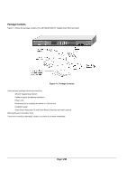
Figure 1-1. Package Contents
........................................................................................................................................................................................
7
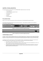
Figure 2-1. Front Panel of the GS724T Gigabit Smart Switch
................................................................................................................................
8
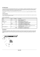
Figure 2-2. Back Panel of the GS724T Gigabit Smart Switch
.................................................................................................................................
8
Figure 3-1. Example of Desktop Switching
...............................................................................................................................................................
11
Figure 3-2. Example of Backbone Switching
...........................................................................................................................................................
12
Figure 4-1. Attaching Mounting Brackets
.................................................................................................................................................................
14
Figure 4-2. Connecting Devices to the Switch
.........................................................................................................................................................
14
Figure 4-3. Installing a Gigabit Ethernet Module into GS724T
.............................................................................................................................
15
Tables
Table 2-1. Front Panel LEDs:
.............................................................................................................................................................................................
9
Table 4-1. Site Requirements
..........................................................................................................................................................................................
13
Table B-1. Troubleshooting Chart
..................................................................................................................................................................................
18