Netgear GS724Tv2 GS724Tv2 Hardware manual - Page 8
PHYSICAL DESCRIPTION, Front and Back Panels, 100/1000 Mbps RJ-45 Ports - gs724t 24 port router
 |
View all Netgear GS724Tv2 manuals
Add to My Manuals
Save this manual to your list of manuals |
Page 8 highlights
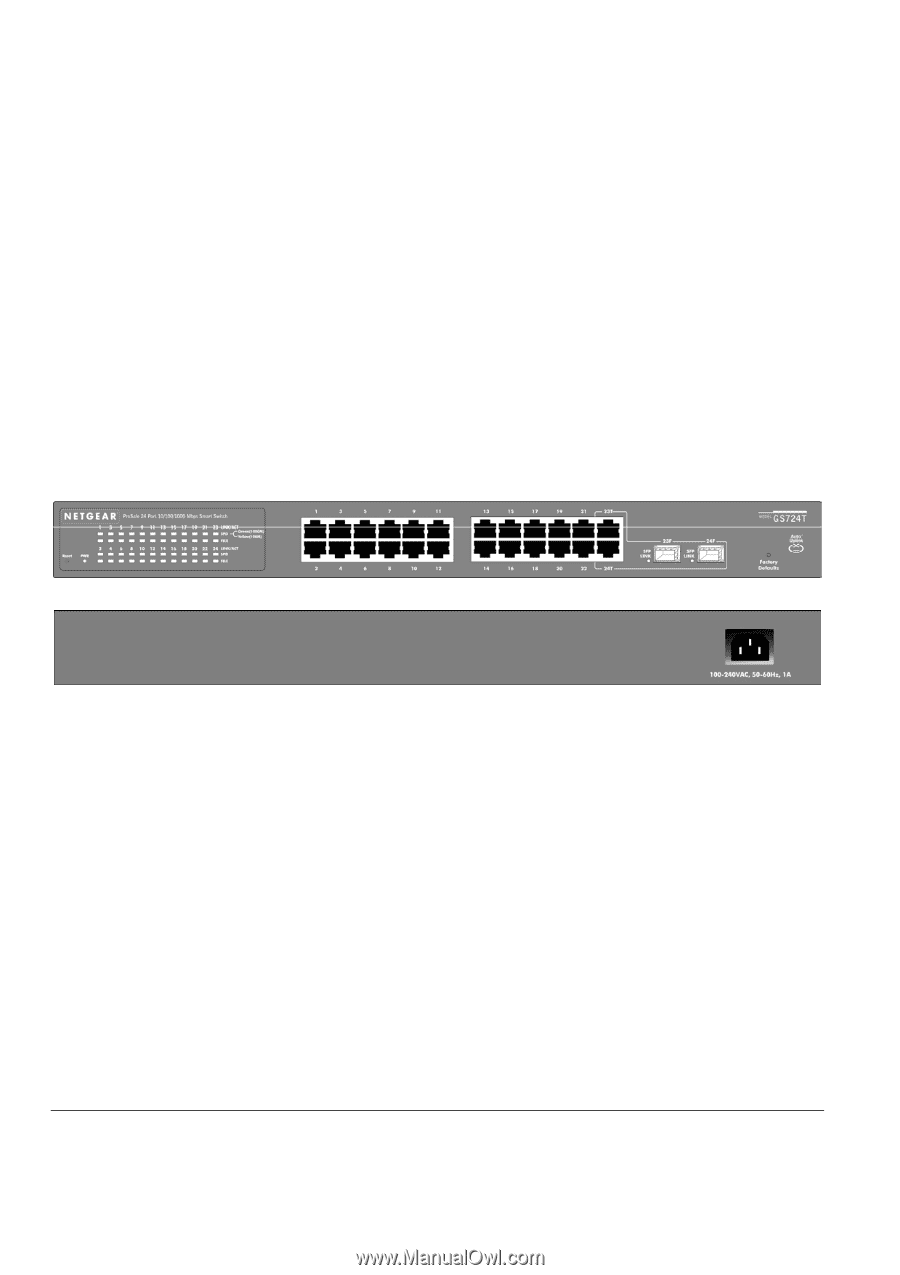
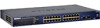
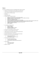
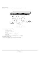
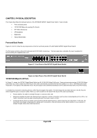
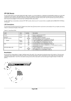
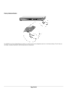
CHAPTER 2: PHYSICAL DESCRIPTION This chapter describes the hardware features of the NETGEAR GS724T Gigabit Smart Switch. Topics include: • Front and back panels • 10/100/1000 Mbps auto-sensing RJ-45 ports • SFP GBIC Module bay • LED descriptions • Reset Button • Factory Defaults Button Front and Back Panels Figures 2-1 and 2-2 show the key components on the front and back panels of the NETGEAR GS724T Gigabit Smart Switch. The front panel contains LEDs and RJ-45 jacks and 2 SFP GBIC module bays. The back panel has a standard AC power receptacle for accommodating the supplied power cord. Figure 2-1. Front Panel of the GS724T Gigabit Smart Switch Figure 2-2. Back Panel of the GS724T Gigabit Smart Switch 10/100/1000 Mbps RJ-45 Ports As Figure 2-1 shows, the GS724T Gigabit Smart Switch has 24 10/100/1000 Mbps RJ-45 ports. These ports are auto-sensing 10/100/1000 Mbps ports: When you insert a cable into an RJ-45 port, the switch automatically ascertains the maximum speed (10 or 100 or 1000 Mbps) and duplex mode (half- or full-duplex) of the attached device. All ports support only unshielded twisted-pair (UTP) cable terminated with an 8-pin RJ-45 plug. To simplify the procedure for attaching devices, all RJ-45 ports support Auto Uplink. This technology lets you attach devices to the RJ-45 ports either straight-through or crossover cables. When you insert a cable into the switch's RJ-45 port, the switch automatically: • Senses whether the cable is a straight-through or crossover cable, and • Determines whether the link to the attached device requires a "normal" connection (such as when connecting the port to a PC) or an "uplink" connection (such as when connecting the port to a router, switch, or hub). • Configures the RJ-45 port to enable communications with the attached device, without requiring user intervention. In this way, the Auto Uplink technology compensates for setting uplink connections, while eliminating concern about whether to use crossover or straight-through cables when attaching devices. Page 8 of 20
-
 1
1 -
2
-
 3
3 -
 4
4 -
 5
5 -
 6
6 -
 7
7 -
 8
8 -
 9
9 -
 10
10 -
 11
11 -
 12
12 -
 13
13 -
14
-
15
-
16
-
17
-
18
-
19
-
20
 |
 |